Friday, December 30, 2011

Kitchen Cabinet

the empty space

When we purchased our house, the kitchen was a nightmare!  I won't go into all of the gory details but the soffits were built without any framing, cabinets were mismatched, glass on some cabinet doors was broken, there were three floors on top of each other, etc.  So before we even moved in I tore the kitchen down to the bare studs and remodeled it.  The only thing I saved from the original kitchen were the granite countertops.

I ordered the cabinets from Cabinet Liquidators.  Their prices were fantastic and the quality is excellent.  They are constructed out of furniture grade plywood with solid maple faces.  To get that same quality from a name brand like Thomasville or KraftMaid you have to upgrade to their premium line which is ridiculously expensive.  Their standard stuff is made out of crap particleboard and is still expensive.  The only downside to Cabinet Liquidators is they have a limited selection of styles and cabinet types.  You are not going to find any odd shaped or custom cabinets.

#%*@ angles!!!

That presented a problem since I was reusing the original countertops.  I had this stupid end piece cut at an odd angle.  The previous owner simply took a skinny cabinet and placed it sideways under that counter, exposing the unfinished side of the cabinet.  It looked terrible.  I wasn't sure what to do with the space, so it sat empty for about two years!  We needed a little more storage so I knew it was time to build a cabinet for that space.  Luckily Cabinet Liquidators sells the cabinet faces by themselves.  I figured I could purchase a face frame and just build the cabinet to fit.  Sounds easy enough, right?
side panel, face frame, kick panels, and shelves from Cabinet Liquidators

First I started off with an easy warm-up project.  I added a piece of trim below the cabinet over the refrigerator to finish that off.
before

trim added

Next it was time for the cabinet.  All of the angles required some very careful measuring and planning.
I had grand plans of rabbet joints and special routered lock joints for the box...but after the first few hours with very little progress, I gave in to butt joints with lots of screws and glue.  After the first day of work (yes, I said FIRST day) I had the cabinet completed but not installed.  I didn't have the courage to try to fit it in place before bed because I knew it wouldn't fit and I wouldn't be able to sleep out of pure frustration!

What did Norm Abram say? Measure six times then run back and forth to the saw until it fits?

the humbling result of about 8 hours of work

the end of day one

The next morning I anxiously tried to slide the cabinet into place.  It fit!  Just required a little sanding in one corner.  I spent the rest of day two getting the cabinet fastened in place, fitting the shelves, installing the door, and adding the finish pieces.

inside view
finished

I am happy with the result but this project sucked!  Took way too long and beat me up.  I haven't been that exhausted after each night since Tough Mudder.  I probably spent about 20 hours building and installing the cabinet.  And now that it's done, I have no idea why it took so long.  It's really only four pieces of wood!  Sixty percent of the time was probably spent measuring and planning.  Getting those mitered edges to line up just right also took a long time.  Oh, and now I remember why I work with metal and not wood.  Metal shards may slice through your skin, but sawdust gets EVERYWHERE!

Bosch jig saw
PS - This project reminded me of how much I love my Bosch jig saw.  It cost way more than you think you should pay for a jig saw but it was worth every penny.  It impresses me every time I use it.  When your jig saw cuts straighter than your table saw, you know it's good.

Friday, December 23, 2011

How to get a $600 radio for $39.99.

Turnigy (aka FlySKy/Imax/Eurgle) 9 channel radio

Uh...wait.  Let me rephrase that.  How to turn a $40 radio into a $600 radio.  Make that a $65 radio.  Hold on, $89.  One more part, $135.  Forgot shipping.  What about the battery?  OK.  How to turn a $193 radio into a $600 radio.

OK, let me explain the prices.  I originally ordered this radio from HobbyKing for $39.99.  That was on backorder so I ordered the same radio shipped from the US from HobbyKing for $64.75.  That was on backorder too.  So then I ordered the same radio off of eBay for $159.95 (I was on a deadline and desperate). Guess what?  Backorder!  I finally found the FlySky (same radio, different name) at HobbyPartz for $89.  Paid an extra $29 for rush delivery.  Then I spent another $53 with shipping for the smartieparts board.  Add 23 more dollars (with shipping)  for a rechargeable battery and you're there.

I have been posting a lot about modifying my FlySky FS-TH9X radio (aka Turnigy 9X) to improve its form and function.  With a few simple modifications, you can give this cheap, yet capable radio the features of a radio costing hundreds more.  This blog is just a list of links to those posts with a brief summary.

  1. Upgrade the firmware - The weakest point of this radio is the buggy and complicated firmware.  Install a board that allows you to upgrade the firmware to a better version.  Bonus, you get a backlight too!
  2. Move the USB plug - Relocate the USB plug on the upgrade board for easier access.
  3. Fix the trainer port - This radio will not work with flight simulator software unless you unplug the TX module.  Adding a resistor will fix this.
  4. Move the antenna - The TX module is hard wired to the antenna.  It should be removable so you can swap in a new module.  See how to move the antenna from the radio to the TX module.
  5. Fix the LED - The indicator LED on the RX is almost impossible to see.  Cut the label and see the light!
  6. Add a rechargeable battery - Who wants to keep replacing 8 NiMH disposable batteries?  Add a rechargeable LiPo battery for economy and longer radio life.

Smartieparts USB Plug Mod

easy access

I covered the installation of the smartieparts board here.  The board has a USB jack that inserts into a slot in the battery compartment.  To program your radio, you open the battery compartment and plug in your USB cable.  This isn't so bad but I thought I could make it a little more convenient to access the USB jack.


charging jack

The radio comes with a charging jack on the side.  Ironically, the radio does not come with a rechargeable battery...or a charger...nor have I ever even seen one available as an option.  So while it seems like a nice feature, it is useless.  Since the charging jack just slides into a slot in the case I figured it would be easy to remove it and put the smartieparts USB jack in its place.

charging jack removed

I pulled the jack out of the case and cut the wires where they were soldered to the circuit board.  The USB jack almost fit right into the hole in the case.  I used a file to open up the hole just a little.  If you go slow, you can get a nice tight snap fit for the USB jack.  I mounted the front of the jack flush with the side of the case.

USB jack fitted to case

The jack needs to stay in place under pressure as the USB cable is plugged in and out.  So I used some epoxy on the bottom of the jack to glue it in place and fill the hole in the case.  I covered the front of the hole with tape to keep the epoxy from running out.  Gave it a few hours to set, added a black marker paint job, and she's done.  Now I can plug my radio into my computer easily without having to open up the battery compartment.  It also opened up some space in the battery compartment which will come in handy when I swap the NiMH battery pack for a rechargeable LiPo.

finished USB jack

FlySky FS-TH9X LED mod

LED next to the "Y" in "SKY"
I have been having some trouble getting my radio to bind with the receiver.  During the process, you need to be able to see the status of a red LED inside the RX case.  Although the case is translucent, the top of the case is covered with a decal.  So to see the LED you need to look through the sides of the case.  It is difficult to see and very inconvenient, especially if the RX is already installed in something.  Since I have been trying to bind my radio over and over for the past few days, that little light was starting to tick me off.  So I looked through the sides, guestimated where the LED was in the case, and cut a window through the decal.  Much better!  The LED now appears nice and bright and I don't have to contort to see it.

Tuesday, December 20, 2011

FlySky FS-TH9X Antenna Mod

FlySky radio, note antenna on top
When you make a copy of a $600 radio and then sell it for under $60, obviously you have to cut some corners.  One of the most annoying things about my budget FlySky radio is that the transmitter module (TX) is hard-wired to the radio antenna.  On just about any other radio, the TX is removable so you can swap out a different unit if you want.  Well on the FlySky (and the other Turnigy/Imax/Eurgle clones) the TX module can be pulled out of the radio case, but then it remains attached by a very thin coaxial wire.  Many aftermarket TX modules have the antenna mounted on the module itself, rather than the radio case.  I figured I could solve the problem on my radio by moving the antenna to the TX, making the module truly removable.

stock TX module

TX removed, note cut wire in upper right

I started by pulling the TX out and cutting the coax wire.  Then I opened the radio case and removed the antenna.  I also opened up the TX case and desoldered the two tiny leads of the coax wire and removed the cut piece of wire.

one screw holds antenna

coax wire inside TX

The next step was to figure out how to securely mount the antenna on the TX case.  I searched my shop and found a fiberglass tube from an old umbrella that fit the inside diameter (9/16") of the antenna base perfectly (and my wife wonders why I keep all of this "junk").  I cut a piece 1 5/16" long, shoved it inside the antenna base and used the stock screw on the antenna to hold it together.

antenna and tube

Next I drilled two holes through the TX cover and into the fiberglass tube for mounting screws.  One more hole was drilled in the TX cover to feed the wire through.

cover and antenna drilled
If I mounted the antenna flush with the TX cover, the antenna would hit the radio case when the module was reinstalled.  So I placed two washers between the TX cover and the antenna for clearance.  Then I grabbed two plastic screws I had laying around and screwed everything together.

antenna mounted

clearance washers

rear view

To make the installation even more secure, I globbed some PC7 (man's best friend) around the antenna mount and onto the TX cover.  I let it set for 24 hours.

PC7 epoxy

The next step was to solder the coax wire back the TX circuit board.  For those that are not familiar with coax wire; there is a single lead through the center of the wire surrounded by a plastic tube.  Around the plastic tube is a woven metal sleeve of wire as a shield.  That is then covered with typical wire coating.  As you can probably tell from the pictures, the wire is tiny.  Stripping and separating the two wires was difficult, even for my favorite stripper!  I ended up cutting the plastic tube off the center wire with an X-Acto and a jewelers loupe.  Both leads then needed to be soldered to two tiny pads on the circuit board that were about 2 mm apart.  Actually, the stripping was a lot harder than the soldering.  I added a little hot glue to the wire to relieve any tension on the solder joints.

coax wire soldered back on

ready to assemble
Finally I reassembled the TX module and plugged it back into the radio.  It is a tight fit under the metal bar on the back of the radio, but once installed there is plenty of clearance.  The antenna still articulates as before.  I tried it out with the receiver and everything still works.  With this mod, the resistor mod, and new firmware installed, my cheapo radio now has all of the capabilities of a much more expensive model.

finished and installed

Monday, December 19, 2011

FlySky FS-TH9X Simulator/Resistor Mod

transmitter module on back or radio
I have about 2 months to build and fly a quadcopter for a project I am working on.  Unfortunately I have never flown any type of remote control aircraft before.  So I am relying heavily on flight simulator software to teach me what I need to know.  One of the first things I purchased along with the quadcopter parts was AeroSim flight simulator software.  It's pretty cool software and one of the few flight sims that simulates multicopter flight.  The first thing I did when my FlySky FS-TH9X radio arrived was plugged it into my laptop to start the multicopter training program.

Of course, it didn't work.  Neither my computer, nor the AeroSim program recognized my radio controller.  After some online searching, I discovered that because of a design flaw in the radio (what do you expect from a $60 radio) the flight simulator port will not work unless you unplug the transmitter module.  So I unplugged the transmitter module and it worked with the software!  No big deal, right?  Almost.  Turns out that although the transmitter can be removed from the radio case, it is still hard-wired to the antenna.  So even though the module is unplugged, it dangles off the back of the radio by a very small wire.  Not only do you risk breaking the wire that way, but every time you plug the module back in you risk pinching the wire.  I could see that sooner or later that wire was probably going to give out.  After some more online research I found a solution.  If you add a resistor to one of the circuit boards, the radio will work with the simulator software without removing the transmitter module.


circuit board on back of radio case

close-up of circuit board
Luckily this is an easy fix.  Open up your radio and unplug the wires connecting the front and back of the case.  There is a circuit board on the back of the case.  On the bottom left of that circuit board there are a number of traces.  That is where the resistor will go.


circuit trace cut

You need to cut the trace before you add the resistor.  Check the picture above to see where to make the cut.  Use a razor blade to cut through the trace then scrape out the copper between the cuts to make sure the circuit is broken.

resistor soldered to base

Next you solder a 1K ohm (brown black red)  resistor to the bottom pin of the trace you cut.  Add some heat shrink tubing to the resistor to protect it from shorts.  Then solder the other end of the resistor to the top pin of the trace you cut.  Put everything back together and you are done.  Now you can plug your radio into a computer and use your flight simulator software without unplugging the transmitter module.
completed resistor mod
A complete explanation of the problem and solution can be found here.  Of course, another solution would be to relocate the antenna to the transmitter module so you could detach it completely from the radio.  See how to do that here.

Sunday, December 18, 2011

FlySky RC Radio Reprogramming

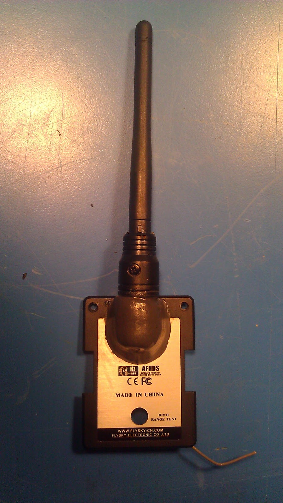
FlySky FS-TH9X radio from hobbypartz.com

I needed a multi-channel radio controller for a drone project I am working on.  Multi-channel radios are expensive, over $600 for something that fit my needs.  Since I am on a tight budget for this project, I started looking for an alternative.  After some research on the web I found the Turnigy 9X radio.  It is a cheap Chinese knock-off of a much more expensive radio.  All of the reviews I read suggested that this radio is an incredible value offering the capabilities of a $600 radio for under $100 (as long as the one you get works, apparently duds are not uncommon).  So I ordered one only to find out it was on back-order for 2-3 weeks.  In addition to the tight budget, I am on a very short deadline and couldn't wait for the backorder to be filled.  So I canceled that order and ordered another one off of eBay.  Found out after I completed the "buy it now" option and paid for expedited shipping, that the eBay seller didn't have any in stock either.  So I canceled that order.  I was starting to panic because I needed a radio and there were none to be found, at least not in my price range.  After some more reading on web I learned that the Turnigy 9X is the exact same radio as the FlySky FS-TH9X, IMax 9x, and the Eurgle 9X.  I finally found the FlySky branded radio available at HobbyPartz.com, paid for rush shipping, and had the radio in hand a few days later.

add-on board from smartieparts.com

Despite the capable hardware of these radios, the software leaves a lot to be desired.  Luckily there is a huge online community of support for this radio.  One of the most common modifications to these radios is to reflash the memory with updated firmware.  The new firmware fixes a number of bugs in the original software and increases the capabilities of the radio.  There are a few different methods for modifying the radio so that it can be reprogrammed.  I chose the add-on board from smartieparts.  The board is a simple screw-on circuit board that not only provides a usb port to allow you to easily upload new firmware onto your radio, but it also adds a backlight to the LCD screen for easier viewing.  I ordered the smartieparts board at the same time as the radio and had it in hand in a few days.

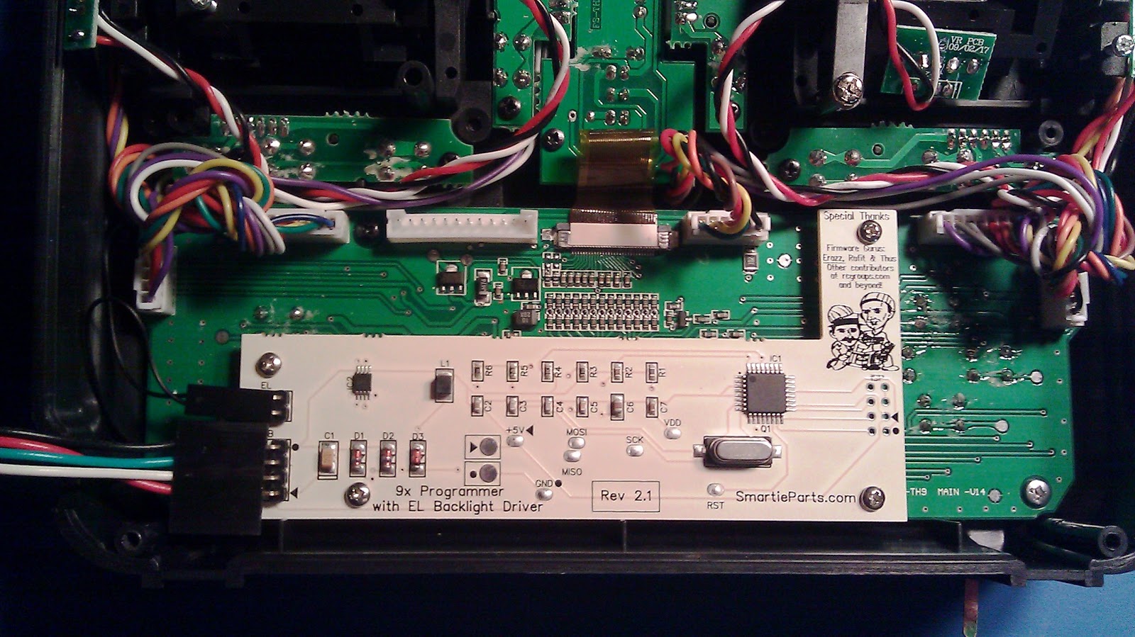
smartieparts board installed

Installation was super easy following the instructions on the website.  Basically open up the radio, remove a few screws, screw in the new board, and slap everything back together.  You then download whichever firmware version you choose, download the eeprom editor software and the usbasp driver to your computer and you are ready to reprogram your radio.  So I do all of that, plug my radio into my computer, upload the new firmware and...nothing.  The editor software gave me an error message stating it couldn't communicate with the radio.  Crap!  I couldn't have screwed up the installation of the smartieparts board because it really is foolproof.  I tried several times, reinstalled all of the software and drivers, even tried a different computer, still nothing.  Finally I vaguely remembered something on the smartieparts website about hardware versions.  Turns out there are two versions of the radio hardware.  The older version has one of the circuit board contact pads in the wrong location.  The newer radios have the contact pad in the correct location.  With the older hardware, the pogo pin on the smartieparts board does not make contact with the required circuit trace and cannot program the radio.  I just assumed that since I had a brand new radio that I just ordered, it must be the most recent version of the hardware.  Oops!  After looking inside the radio, I realized that I indeed had the older version of the hardware.

incorrect location of contact pad

The recommended fix is to solder a wire from the correct circuit trace on the radio directly to the smartieparts board.  Well first of all that means that the board will be semi-permanently attached to the radio.  And it also requires soldering to some very small surface mount components on the radio circuit board.  I am a pretty experienced solderer and I have some very good equipment, and even I was skeptical about my chances of success at that job.  I figured there must be a better way.  I decided to try to put a contact pad in the correct location on the radio circuit board so that the smartieparts board could simply be screwed in and work as intended.

I started by cutting through the original contact pad with an X-Acto knife and a jewelers loupe to disconnect it from the wrong trace.  I had to use one of the thicker X-Acto blades as the thinner blades wobbled too much and risked slipping and damaging the board.  After I cut through the pad I checked with a multimeter to make sure there was no electrical contact with the old trace.  Next I used the X-Acto to carefully scrape the protective covering off of the correct trace so I could solder to it. 

old pad cut and correct trace ready for solder

I tried to bridge some solder between the old contact and the propper trace.  No luck.  I needed some copper to bridge the gap.  So I cut some copper foil off of a scrap circut board I had with a chisel blade and cut it down to size.

copper foil cut as new contact pad

Then I soldered it between the old contact pad and the correct trace.  One last check with the multimeter to make sure the new contact pad was connected to the correct trace on the microprocessor.  Looked good so I put everything back together and crossed my fingers as I tried again to reprogram my radio. 

new contact pad - not pretty but it worked

Success!  The software indicated the new firmware was loading.  When it was done, my radio screen flashed to life with the new firmware logo.  I was able to get the smartieparts board to work with version 1 hardware without soldering it directly to the radio.  Now my radio has total flexibility.  I can add any of dozens of firmware versions and update the radio at any time.  I can also configure the radio controls from my computer without having to go through all of the menus on the radio screen.  For a total investment of under $150, I now have a radio with the capabilities of one costing 4 times as much.

firmware successfully loaded
new firmware start up screen, backlight works too!

I am really starting to like this radio.  Just a few more tweaks and it will be ready to go.  One slight annoyance with this radio is it will not work with simulator software unless you unplug the TX module.  Not a big deal but it is slightly inconvenient.  Adding a resistor will correct this.  And unfortunately when you unplug the TX module, it is still stuck to the radio because it is hard wired to the antenna.  I am going to move the antenna from the radio to the TX module to fix that problem as well.  Click here for the resistor mod.  Click here for the antenna mod.  I also relocated the USB port from the smartieparts board to the side of the radio case.  Check that out here.

Sunday, December 11, 2011

Stupid Sock Creature

"Monkey Boy" I and II

Yes, real men can sew.  I was looking for something to make for my oldest daughter for her second birthday in 2006.  I came across Stupid Sock Creatures in the bookstore.  Great book.  It explains how to make odd looking stuffed animals out of socks.  Not only does it include patterns but it also goes into general construction techniques so you can make up your own creature.  Intended for beginners, the book is very thorough and assumes you know nothing about sewing.  I hadn't touched a needle and thread for over a decade and I had no problem knocking one out in an evening.

I chose "Wronky" from the book for the first one (pink).  I followed the directions almost word for word.  He turned out great but I think he's a little under stuffed.  I may need to perform a little surgery soon.  I gave him to my daughter and she immediately named him Monkey Boy.  Last June I made the second one (black and pink) for my youngest daughter's third birthday based on "Owlsley" from the book.  This time I changed up the pattern a little making the legs shorter, the arms longer, eliminating the tag and making it a cyclops.  Following her sister's lead, she also named it Monkey Boy.

The hardest part is finding the right socks.  Most socks are truly boring.  And when you find interesting socks, they are often too thin or too soft to make good stuffed animals.  Ideally you want heavy cotton or wool socks with a nice pattern to them.  Your best bet is to go to a dedicated sock store; I had a tough time finding what I was looking for in department stores.  "Monkey Boy I" is made out of a pair of super soft fuzzy socks.  Unfortunately the fabric doesn't hold stitches too well and he has had to make a few trips to the stuffed animal hospital.  "Monkey Boy II" is made from tougher socks but they are a little on the thin side.  Time will tell how he holds up.  This was a quick and easy project.  Both Monkey Boys hold a place of honor among their favorite stuffed animals.  Check out the Stupid Creatures website for more ideas.

Sunday, December 4, 2011

Shotgun Repair

Spanish side by side .410

Time for some gunsmithing!  A couple of weeks ago my buddy called me asking if I knew of any good gunsmiths in the area.  He had a .410 side by side shotgun with a broken safety.  When you loaded and cocked the gun, the safety would automatically set but only for one trigger.  The other trigger was ready to fire and could not be put on safe.  Unfortunately I didn't know any gunsmiths but I have a a fairly complete set of gunsmithing tools and I have done some firearm repairs before, so I offered to take a look at it.


The shotgun turned out to be a mystery.  It was labeled "Jana-Denver, CO" but also said "Made in Spain"?  A little searching on the web (especially at Shotgunworld.com) told me that Jana was an importer, now long out of business.  They imported shotguns from a variety of manufacturers.  But who made this one?  It looked to be a pretty decent shotgun with lots of hand engraving on the metal, a color case hardened finish, and a nice walnut stock.  Researching some proof marks on the barrel indicated that it was most likely made by Loyola.  That wasn't much help since I couldn't find any information on Loyola shotguns or any parts diagrams.  I've never been inside a shotgun before so I wasn't sure how I was going to disassemble this thing, let alone repair it without a decent parts diagram.  I convinced myself "How hard could it be?" and started the disassembly.
hand engraving under the action

Well, it turns out it was harder than I thought.  No matter which screws I removed, I could not get the action out of the stock.  Dejected, I put the shotgun aside.  A day or two later I awoke at 3:00 AM and could not get back to sleep.  The shotgun was haunting me.  Refusing to admit defeat, I crawled down to the basement for a second attempt.  I found the answer by accident.  As I was manipulating the action the trigger guard moved.  For a second, I thought I had broken the weld on the trigger guard.  Then I realized the end of the trigger guard was actually threaded into the action.  I spun the trigger guard off, removed one more screw that was hidden under the trigger guard, and voila!  The action came apart and off the stock.


the mysterious threaded trigger guard

The safety problem was ridiculously simple.  Each trigger is a lever.  The safety is simply a bar that slides over the top of the levers to block any upward movement.  The bar is a screw.  Somehow the screw had backed itself out and was only blocking one trigger lever.  I pulled out the screw, cleaned it, and screwed it back in with a little Loctite until it blocked both levers.  So about 2 hours of work trying to get the action off, and 2 minutes to fix the broken safety.


safety screw

safe and fire positions over the triggers

With that problem solved, I noticed the recoil pad was dry rotted and starting to crumble.  I needed more of a challenge since the safety problem was too easy of a fix.  So with an OK from my buddy I figured I would attempt to fit my first recoil pad.  Obviously I couldn't order a direct replacement for this uncommon shotgun.  I measured the original recoil pad and looked for a replacement.  The stock is relatively small and narrow so I ordered the smallest recoil pad I could find from Pachmayr.  The website had a pretty good set of instructions on how to properly fit their pads.  It sounded like something I could handle.


original rotten recoil pad

First I carefully removed the old pad.  That was no simple task as the screws were hidden beneath the pad and it was glued on as well.  Luckily I managed to get the old one off without damaging the stock.  Next, I filled the old screw holes.  I drilled them out a little, glued bamboo skewers in the holes, and cut them flush.  To prep the recoil pad for screws, I used a transfer punch inserted from the back of the pad to make a dimple in the center of the screw hole on the face of the pad.  I used an x-acto knife to carefully slice between the horizontal ridges on the face of the pad where the dimple was, and pushed the punch through. I oiled the screws before inserting them into the pad.  The screws disappeared beneath the pad without a trace. Then I carefully lined up the pad, marked the locations for the new holes, and drilled.


old screw holes filled

new holes drilled

Next I temporarily attached the recoil pad and scribed the outline of the stock on the back of the pad with an x-acto knife.  There was a fair amount of extra material and I doubted if I could take it down to size without it looking like I butchered it.


pad marked for grinding

Then I removed the pad and sanded off the bulk of the material on my stationary belt sander with an 80 grit belt.  The brown part of the pad looked and smelled a lot like pencil erasers as I ground it down.  Next I used 120 grit paper on my stationary disk sander to take the pad just shy of the stock marks.  The grinding went fairly quickly and I noticed the finish on the pad looked pretty good after a pass with the 120 grit.  I was feeling pretty confident at this point.

after rough grinding

I screwed the pad back on to the stock for the last time.  Then I wrapped the end of the stock in a layer of painters tape to protect the finish.  I had maybe 1/32" of material left to remove.  I hand sanded with 150 grit paper wrapped around a block of aluminum until I started to sand the tape.  Finally, I finished up with 320 grit wet/dry paper lubricated with a few drops of kerosene.  One last wipe with kerosene to clean the pad and I was done.

after final hand sanding


My one mistake was not following the angle of the stock on the toe of the recoil pad.  I squared mine off.  It doesn't look bad, I just think and angled toe would have looked more professional.  Oh well, live and learn.  Overall I am extremely happy with the results.  Much easier than I expected and you really can't tell that I ground the pad down.  It looks as if it was made that size from the start.  I actually impressed myself with this job!


look ma, no screws!

a job well done