Monday, October 29, 2012

Custom Ruger 10/22 Part III - Modifications


In Part I I machined the receiver.  Part II listed all of the parts I used to build the rifle.  In this part we'll look at the modifications I made to hopefully improve accuracy and reliability.

Ruger target bolt assembly

The bolt usually receives a lot of attention in these guns.  As I stated in Part II, I purchased a Ruger target bolt.  Besides the polished side, I'm not sure what the difference is between the target and standard bolts.  Given the $4 difference in price, I'm guessing not much.  The first thing most people recommend is replacing the extractor for more reliable ejection of spent cases from the tighter chambers of aftermarket barrels.  I chose the Clark Custom extractor.  Installation took just a few minutes.

Clark extractor

The next thing usually done to the stock bolt is to reduce the headspace to about 0.043".  This makes sure that each round is completely seated in the chamber and the bolt makes full contact with the base of the ammunition; thereby increasing accuracy.  I roughly measured my headspace to be about 0.0445".  But when I lowered the bolt on a CCI standard velocity round, the round had no room to move at all.  I couldn't perceive any excessive headspace.  So I'm going to leave it alone for now and see how she shoots.  Perhaps the target bolts are hand selected to have tighter headspace than the stock units.

no extra headspace here

The last thing I did to the bolt was to round off the back of the bolt.  When the bolt retracts, the back of it hits the hammer and cocks it back.  The stock bolt hits the hammer at a sharp angle.  If you ease the angle of the bolt, then it slides over the hammer rather than slamming into it.  This reduces friction, recoil and wear.  A few minutes on the belt sander gave it a nice rounded edge.  A little polishing with the Dremel made it nice and smooth.  I can already feel the improvement; much easier to cock the rifle now.


stock bolt (Left) and modified bolt (Right)

See the stock magazine release?  Me neither.

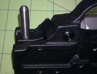
The magazine release button leaves a lot to be desired.  I read a forum post where someone said you need a degree in proctology to release the magazine; not far from the truth.  After a few decades Ruger finally caught on and new trigger assemblies come with an extended magazine release.  My older trigger assembly has the flush mag release.  There are dozens of aftermarket extended magazine releases available; everything from little nubs that barely protrude to long arms that wrap around the entire trigger guard.  I decided to make my own modeled after the Clarke Custom model.

Clark mag release

I drilled and tapped the stock mag release 1/4"-20.  Then I grabbed a piece of 1/4" stainless rod and threaded one end to match.  Cut it 7/8" long past the threads, rounded the end on my lathe, and polished.  Cut the threads to length and secured the pieces together with Loctite.  Looks great and works even better.

ready to assemble

extended mag release

After investing in a target barrel, I want to take good care of it.  If you can avoid it, you should never clean from the muzzle of the barrel; you might ruin the crown.  The way the Ruger 10/22 is constructed, it is impossible to clean from the breach end unless you use a bore snake or similar.  In order to access the breach end, some people drill a hole in the back of the Ruger receiver to pass a cleaning rod through.  After I drilled the barrel hole I left the set up as is and used an extra long drill bit to drill the back of the receiver exactly in the center of the bore.  Most people just drill a 1/4" hole but I drilled and tapped a 5/16"-18 hole.  That way I still have about a 1/4" hole for access but I can close off the hole with a 5/16" grub screw when I am done.  Now to clean I remove the action from the stock, remove the trigger group and bolt assembly, and clean the barrel from the back of the receiver.  The stainless grub screw I made ensures that dirt and gas don't blow out the back of the receiver right by my face.

access hole to clean barrel

sealed with a grub screw

Well that's it for the build.  The rifle is done!  In Part V we'll see if all this work paid off.  I'll check accuracy at 50 yards with a variety of ammo.  Maybe we'll even take the best ammo out to 100 yards if the conditions are right.  Stay tuned!

Sunday, October 28, 2012

Custom Ruger 10/22 Part II - The Parts


In Part I I finished the machining on the receiver.  Now we'll add the parts and get this thing ready to shoot!

Receiver
As I mentioned in the first post, I used a Razor receiver from Select Fire, LLC that I finished myself.  The build can be seen in Part I.

finished Razor 10/22 receiver

Barrel
The barrel needed to be very accurate.  I also wanted a short bull barrel configuration.  I chose the 18" Adams & Bennett barrel in blued steel.  It received incredible reviews and reports of excellent accuracy.  It features a Bentz chamber which is tighter than a stock chamber for better accuracy but a little larger than a match chamber for reliable feeding in semi-autos.  Accuracy results can be seen in Part IV.  The barrel retainer is from Tactical Solutions; retainer screws are stock Ruger items.

Adams & Bennett barrel

Stock
I would have loved a target stock like a Bell & Carlson but I just couldn't justify the cost.  I saw a few rifles assembled on  Hogue OverMolded stocks and they looked great so I decided to go with that  The receiver fits the stock nice and tight; no slop at all and the rubberized coating gives a perfect grip for my sweaty hands.  The barrel is free-floated all the way back to about 1.5" from the receiver.  I added a Caldwell 6-9" XLA pivoting bipod for steady shots.  It attaches in seconds to the front sling swivel stud.  The takedown screw is a stock Ruger item.


Hogue stock and Caldwell bipod

Receiver parts
The bolt assembly is a stock Ruger target bolt.  I think the only difference in the target bolt is the visible side is polished.  That side doesn't even contact anything so I doubt that it is any more accurate that a standard bolt.  Perhaps the headspace is a bit tighter; standard bolts are known for excessive headspace.  Check the pic below, doesn't look like there is much room for improvement.  You don't want the headspace any lower than 0.43".  I measured the headspace on my bolt at 0.0445"; close enough.  I added a Clark Custom extractor for more reliable extraction.  The bolt handle assembly is from Power Custom.  The heavier weight of the handle and smooth guide rod should calm the cycling down.  I replaced the steel bolt stop pin with a polyurethane bolt buffer from Select Fire.  This part quiets the action, reduces recoil, and most importantly prevents wear on the bolt and receiver.  A definite must have!  Receiver cross pins are stock Ruger items.  Update:  I also installed a much needed firing pin from KIDD Innovative Design.  Check Part IV for an explanation on why I needed the firing pin.

Ruger target bolt assembly

Ruger target bolt with CCI standard velocity ammo.
Doesn't look like there is any extra headspace.

Power Custom bolt handle

polyurethane bolt buffer

Trigger Assembly
Rather than mess around with purchasing custom trigger parts and fitting them myself, I purchased a complete trigger assembly from Clark Custom Guns.  Clarke is known for their custom 10/22 work.  It is a fantastic trigger, nice and crisp; 2 lbs 10 oz out of the box with zero overtravel.   As a bonus they use the older Ruger metal trigger housing; new factory trigger housings are plastic.  Even though the new plastic housings are almost indestructible, I prefer the metal.  Also, the bolt release is modified to you can release the bolt by pulling back on the bolt handle; not by fumbling for the bolt release tab.  Overall the cost was about the same as buying a stock trigger assembly and aftermarket trigger parts and installing it myself.

Ruger trigger assembly modified by Clark Custom

Scope
One of these days I'm going to purchase a premium scope.  But for now I'm on a budget.  So I settled for a BSA Sweet 22 3-9x40.  Price was right and it has an adjustable objective which I think is critical for a 22.  I needed high magnification for optimum precision but anything larger than a 3-9 would be too large for such a small rifle.  It comes with three different elevation turrets; each one for a different weight bullet.  We'll see if I can match any of the premarked ranges on them to my ammo. Hopefully I can squeeze some decent accuracy out of this thing.  I used a set of standard height rings I had laying around, not sure what brand they are.  With the height of the scope rail the 40mm objective just clears the barrel.

BSA Sweet 22 3-9x40 scope
(yes I know the scope is in sideways, oops)

All together.  I hope it shoots as good as it looks!

The final product looks great.  It's pretty heavy for a .22 at 8.5 lbs but that should help keep the rifle nice and steady.  In Part III, we'll look at a few modifications I made during assembly to squeeze out the last bit of accuracy and reliability.  We'll address one problem in Part IV.  And finally we'll see if it all payed off in Part V.

Custom Ruger 10/22 Part I - Machining the Receiver

stock Ruger 10/22


I've always wanted a Ruger 10/22.  It's one of those iconic rifles that has everyone should have.  It has stood the test of time as a reliable, accurate, fun rifle.  As a .22 rimfire it's cheap to shoot, and best of all the aftermarket support for this rifle is HUGE!  You can literally replace every single part of the rifle with an aftermarket part creating exactly the rifle you want.  It's the Burger King ("Have it Your Way") of rifles!  You can have almost as much fun modifying the rifle as you can shooting it.

So when it came time to get my own 10/22, I had a few choices.  I could buy a stock one, then spend hundreds on upgrading it to the custom piece I wanted.  I could shell out big money for a custom one already modified.  Or I could start from scratch and build my own.  I opted for the challenge of building my own.  Not just choosing and assembling every part, but making the receiver as well.

Razor 10/22 receiver blank

Rather than start with a hunk of aluminum and machine the entire receiver, I started with a Razor 80% 10/22 receiver from Select Fire, LLC.  Basically, it is a partially finished Ruger 10/22 receiver.  You perform the steps to complete the receiver into a functioning firearm.  Perhaps in the future I will make one completely from scratch, but the Razor will save me so much time it's a no-brainer.  Before anyone asks, this is all perfectly legal.  The Razor is not a functioning firearm.  It is merely a hunk of metal until you finish the machining to make it into a firearm.  Therefore, the sale does not need to take place though an FFL.  And yes, it is perfectly legal to make your own firearm so long as 1) you can legally own a firearm (i.e. you are not a felon), 2) the firearm you make is legal to own, and 3) you are building it for yourself, not to sell.  If you don't believe me, check out the official statement from the BATFE.

The Razor has some nice features.  It is made from bar stock 6065-T6 aluminum on cnc machines (not cast).  It can be purchased already anodized, saving me the time and money of applying the myself.  It also sports an integrated rail and riser making for rock solid and repeatable optics mounting.  They claim the rail is military standard 20 mm (i.e. picatinny rail), but picatinny rail has flat bottom grooves.  The Razor has rounded grooves.  Maybe it's a hybird made to fit picatinny and weaver scope rings?

I'm not going to go into great detail on finishing the receiver.  Adequate directions and dimensions can be found on their website.  The directions assume you are using a drill press and their drilling jig (sold separately).  However, if you have a mill, the jig is unnecessary.  Machining is pretty easy, some drilling, some tapping, some clean-up work.  No milling involved.  All straightforward, no explanation needed.  The hardest part was drilling the barrel hole.  The drilling itself wasn't hard but the set up took me about 2 hours to get perfect.

receiver secured for drilling

It is critical that the barrel hole is perfectly parallel to the top and sides of the receiver or the barrel will end up on an angle.  So take the extra time and be sure the set up is perfect.  I used precision angle plates and 1-2-3 blocks to make sure everything was square.  Then I held everything in place with c-clamps and triple checked everything with a machinist square.  This ended up in a rock-solid setup.

front view of set up

this thing isn't moving anywhere

The Razor used to ship with the center marked for the barrel hole.  Now it does not.  I had an older model with the center marked.  A #12 drill bit fit the hole perfectly.  To line things up with my collet, I chucked the #12 drill upside down and adjusted the table until I could lower the bit into the receiver without feeling or hearing the bit hit the sides of the hole.  Once lined up I locked the tables and started drilling.  I started with a 1/8" drill bit and worked my up to 1/2" in 1/16" steps.  Then I drilled the 9/16", 5/8" and 11/16" holes with end mills.  I spun the end mills at 1500 rpm and used kerosene as a lubricant.  I only cut about 1/16" at a time, cleaning the chips after each peck.  The result was a very clean hole.  The barrel fit perfectly; a nice tight fit with no play.  I doubt I could have done much better even if I had reamed the final hole.

centering collet to drill barrel hole

completed barrel hole

the barrel fits!

The finished receiver came out great.  All of the machining is hidden by the parts, so the anodized finish is left unmarred.  Better than the stock Ruger item because the scope rail is integrated into the receiver.  All that is left is to add your parts and go shooting!  Check out the links below to see the rest of the build.

Part II - Parts
Part III - Modifications
Part IV - Troubleshooting
Part V - Accuracy


finished receiver - side view

front view

bottom view

rear view

Friday, October 12, 2012

FPV System

FPV camera on ArduCopter

I built an ArduCopter for a research project I am working on.  One requirement is the ability to pilot the copter remotely.  To do that I need a powerful FPV (First Person View) system.  An FPV system gives you a view from the remote vehicle you are piloting.  That way you can fly the copter beyond your line of sight (although it's not actually legal to fly a remote vehicle out of sight...yet).

HobbyKing FPV system

I was on a tight budget so for our first prototype we went with a complete system from HobbyKing.  It's a pretty basic system with a 900Mhz 1.5W transmitter with a Sony 520 TV line color CCD camera.  The camera is a bit large compared to more expensive models and the camera circuitry is completely exposed.  The transmitter is probably larger and heavier than it needs to be.  And the transmitter antenna is way too big to be practical on a vehicle.  But with relatively high resolution and a powerful transmitter, it should do the trick.  It came without any instructions but luckily it wasn't too hard to figure out how to wire it up.

wiring
The system was pretty easy to set up.  The receiver power supply came with a foreign power plug so I cut it off and spliced in a US plug from an old power cord.  Just plug the camera and transmitter into the included wiring harness and add 12v DC.  I used a 11.1v LiPo battery.  On the receiver side, just plug in the 12v DC power supply and attach the RCA cable to your monitor.  Make sure the transmitter and receiver are on the same channel, and you should see an image on the monitor.  I tried it out using my television and it worked.  The picture was actually quite good.

camera image wirelessly transmitted to a TV

Getting it to work with the TV is easy.  The signal from the receiver is analog and so is my old TV.  The real trick is getting the receiver to work with my laptop.  For that you need to convert the analog signal to a digital signal that your computer can use.  Based on some online recommendations, I used an EasyCap 2.0 to import the image to my laptop.  The EasyCap plugs into your USB port and has RCA and S-video cables to import analog signals.  I installed the drivers and software, plugged it into my laptop and attached the receiver.  Using the software, I was able to see the image from the camera.

EasyCap and receiver attached to laptop sending a live wireless image of my mill

With that hurdle crossed, the next step was to see if I could get the image imported into the Mission Planner software.  The Mission Planner software displays all of the gauges and coordinates while flying the ArduCopter.  Incorporating the FPV image into the software allows you to see all of the flight information and the view from the ArduCopter all on the same screen.  I was able to easily import the image by changing a few settings in the Configuration tab following these instructions.

live camera image successfully imported into the Mission Planner software

To mount the camera to the ArduCopter I used this mount from Hobby King.  I didn't need the pan function so I only used one servo to control the camera tilt.  The mount is a bit flimsy, especially the servo linkage, but it works fine for our prototype.  I mounted it between the front motor arms with some scrap aluminum.  It is clamped to the arms so I didn't have to drill any holes which might weaken the arms.  The servo plugs into an extra channel on my receiver and I use the pit trim pot on my radio to control the tilt of the camera.  I soldered a male JST battery pigtail to the power distribution board to supply 11.1v to the camera and transmitter.

camera and mount

The final step was testing the range of the wireless video signal.  I mounted the transmitter to the roof of my car.  I set up the base station, running the laptop and the receiver off of AC power with the receiver up about 15 feet on a pole.  Then I proceeded to drive away maintaining cell phone contact with someone at the base station.  We lost the image about 1400 feet from the base station in a dense urban environment.  Given the 1.5 W power of the transmitter, I expected slightly better distance.  I believe that with a signal tracking directional antenna on the base station, elevated above the roof lines giving line of sight to the arducopter, distance will be greatly improved.

This set up was just a proof of concept for our prototype.  I intend to upgrade to a smaller sealed HD camera, a smaller and lighter transmitter, better receiver, and an antenna tracking system on the receiver to prevent signal loss.  I'll keep you posted.