Friday, June 22, 2012

Motorized Bicycle - Chain Tensioner

custom chain tensioner

If you are very lucky, when you mount the motor you will be able to adjust the chain length perfectly so that both the pedal chain and the motor chain are taught without any need for a chain tensioner.  Chances are, you won't be that lucky.  I needed a chain tensioner to keep from throwing the motor chain.  Unfortunately, the chain tensioner that came with the motor kit was the ugliest monstrosity I had ever seen.  If I was Grubee I would be embarrassed to include it with the motor kit.

stock chain tensioner

before finishing

First, the stock unit would not have fit the oversized chainstay anyway.  Second, I'm pretty sure the plastic wheel would have been quickly chewed to bits by the moving chain.  There are aftermarket solutions which are much more elegant, but again they cost a lot.  So I decided to make my own.  I started with a length of 3/16" x 1" aluminum bar stock cut to length.  Then I milled a 3/8" slot for an idler sprocket where the bracket met the chain.  I drilled and tapped the bottom of the bar to mount to the hub-brake mount.  To mount the top of the bracket, I drilled and tapped again and used one of the motor mount caps to secure it to the seat stay.

lower mounting


repurposed motor mount for top mounting

Surprisingly, the hardest part was finding an appropriate idler sprocket.  Most of the ones I could find were way too large.  I finally found a 10 tooth sprocket on Amazon that was a replacement part for a lawnmower.  It worked perfectly but I had to grind down the bolt head a little to clear the spokes.  When it was all finished I threw it in the blast cabinet to give it a brushed look that matched the motor.  The new tensioner is rock solid, easy to adjust, and only cost about $10.

idler sprocket


Motorized Bicycle - Attaching the Sprocket

motor sprocket

Here's a bit of a warning for anyone wanting to attempt this on their own.  The manual states that you may have to open up the diameter of the hole in the center of the sprocket to clear your hub.  The hole needs to be perfectly centered or your sprocket will run out of true and you will throw your chain.  The manual recommends taking it to a machine shop and having the work done on an engine lathe.  Good advice, but they should do a better job of making people aware of this before they purchase the kit.  Of course, the sprocket didn't fit over my hub.  Luckily I am equipped to deal with this, but unless you have access to machine tools, you may need to plan accordingly.

I ended up securing the sprocket on my mill with some hold-downs and using a fly cutter to open up the hub hole about 1/16".  Two heavy rubber gaskets (I think they are just pieces of old car tires) go on either sides of the spokes and then the sprocket is bolted through the spokes to some metal plates.  The rubber gaskets were warped which made lining everything up evenly very difficult.  I torqued down the bolts and left them overnight to let the gaskets settle.  The next day I loosened the sprocket and carefully centered the sprocket over the hub.  I gradually tightened all of the bolts (several times, as the sprocket kept shifting), then loosened one at a time and added blue Loctite to keep them from coming loose.  A quick spin of the wheel confirmed that everything was centered.  This was one of those steps that looked like it should take 15 minutes but ended up taking a few hours.  Several companies make sprocket adapters for these motors that make attaching the sprocket much easier.  Of course they cost more but it may be worth it just to save on time and frustration.

front view

rear view

Motorized Bicycle - Index

completed motorized bicycle

Every year my car club The Road Lords, puts on Scarlett Fever.  Scarlett Fever is a benefit car show/concert/art auction for our girl Scarlett who is battling Rett Syndrome.  During the show we raffle off items to help raise funds for Scarlett's medical expenses.  This year, I offered to build a motorized bicycle for the raffle.  I have always wanted to build a motorized bicycle but it wasn't until I saw an article in Make magazine that I realized there were relatively inexpensive kits available that should make it a pretty easy process.  I really couldn't justify building one for myself, but the raffle gave me the perfect excuse.  Now I could satisfy my urge to build and ride one without incurring the expense or worrying about storing it in my overcrowded garage afterwards.

1903 by Felt

I could have used any bike but I have been enamored by the Felt cruisers ever since I first saw them.  They aren't cheap, but they are built with quality parts and the styling can't be beat.  Their 1903 was just begging for a motor!  With the springer front fork, large leather seat, huge top tube, pinstriping, and fat white tires, it looked like one of the early Harley's.  I was fortunate to find one locally at Cags Cycles.

Grubee Skyhawk motor kit
With the bicycle picked out, I needed a motor.  Their are dozens of places online that sell chinese motor kits that include everything you need to add a motor to your bicycle.  After researching some online forums I placed an order for a 66cc Grubee Skyhawk kit from Gasbike.net.  Ordering anything cheap from China is always a crapshoot but this kit got pretty good reviews online.  It arrived a few days later packaged in typical fashion; slopped in grease, wrapped in used bubble wrap, and litterally thrown into a box.  Despite that, everything arrived in one piece and without any missing parts.  The manual is a bunch of faded photocopies written in Chinglish so you better have some idea of what you are doing before you start.

Just a word or warning.  IF you have a bicycle with standard geometry the motor kit could install in a few hours by anyone with moderate mechanical skills.  But because of the unique styling of the Felt 1903, nothing fit out of the box.  There was a significant amount of machining involved to get the motor to work with bike.  This motor, with this bike, is not a project for a beginner.  There is a lot to this build, so I have broken it up into parts.  Click on the links below to view the build.

Part I - Mounting the Motor
Part II - Attaching the Sprocket
Part III - Chain Tensioner
Part IV - Fuel Tank
Part V - Other Parts
Part VI - Epilogue

Sunday, May 20, 2012

Magnetic Shop Light

finished light

I still haven't set up the lighting in my shop.  So I needed a small spot light that I could mount to my mill and/or lathe to provide extra light when needed.  I had all the parts lying around; total cost $0.00.  This was a pretty simple project so I'll let the pictures do the talking.

rescued from the trash
the parts; lamp and Harbor Freight magnet

gently coaxed from the base and disassembled, had to desolder
the wire from the light socket
epoxied piece of threaded tube from old pedestal lamp into neck
milled hole in neck for power cord

drilled magnet to fit over rod and fastened it in place
reassembled
finished product in action

The light works great.  The magnet is ridiculously strong; it's not coming off until you want it to.  Now I can actually see what I'm doing.

Saturday, April 28, 2012

Soldering Fume Extractor

Fume Extractor
As I started doing more electronics work I realized that a fume extractor would come in really handy for sucking the flux fumes from my face.  So I dug through the junk pile and built this one.  Everything was from my pile of parts with the exception of the charcoal filter.

rear view
The aluminum case was from an old air monitoring unit.  Suction comes from an old 12v computer fan.  I cut the hole with a large hole saw and covered the fan with a grate from some old piece of equipment.
inside view

switch and power jack
The circuit is pretty simple.  Just a switch, 1/8" female power jack, and a 7812 12v regulator; all reused from junked equipment.  Power comes from a 16.5v 300mA switching power supply from a junked rechargeable vacuum.  With the voltage regulator, you can power it with anything up to 30v.

charcoal filter
I used some rivet nuts in the case to make the cover removable with thumb screws.  The center of the cover was cut out with nibblers.  I purchased a charcoal filter originally intended for a smokeless ashtray and inserted it under the cover.  With the filter it doesn't just blow the fumes away, it should capture the fumes resulting in cleaner air.  Finally, I mounted it to a gooseneck from an old desk lamp.  Easy project, works great, and keeps you healthy!


Thursday, April 19, 2012

FlySky FS-TH9X Battery Upgrade

Rechargeable battery upgrade for FlySky transmitter

The manual for my FlySky radio shows a nice picture of a charger and rechargeable NiMH battery pack.  But it doesn't come with one.  And there isn't one available as an option from the seller.  Instead it comes with a battery holder for 8 AA NiMH batteries.  It works well enough but NiMH batteries have limited capacity, discharge relatively quickly, don't hold their charge even when not in use, and don't recharge very well.  Luckily we can easily swap out the 8 AA's for a much better LiPo battery pack.  With increased capacity, the LiPo pack will last a lot longer than a bunch of AA's and it can be recharged over and over again. There are just a few things to consider when purchasing a replacement pack.

lame!

Battery Size
The dimensions of the battery compartment are 112 x 32 x 25mm.  Make sure the pack you order will fit your receiver.

Capacity
Your best NiMH batteries can provide around 2500 mAh.  But your typical AA is more likely to be rated at around 1200-1500 mAh.  Get the largest capacity LiPo that will fit for the longest run time.

Discharge Rate
This one is important.  Standard LiPo batteries can discharge 30-40 times their capacity.  That means a 2000 mAh battery can output 60-80 amps at one time.  Obviously your radio will never draw that much current but the pack is capable of supplying more than enough current to fry your transmitter.  Select a battery made for radio transmitters with a low (1C) discharge rate.

Voltage
Eight AA batteries can supply 12 volts.  But they discharge quickly, so you never actually run at 12v for long.  More realistically they run at about 1.2 volts per cell or 9.6 volts total.  A 3 cell LiPo is only rated at 11.1 volts (3.7 volts per cell).  That is plenty to run your transmitter, especially since it stays at that level for a long time.  However, when fully charged, a 3 cell LiPo can provide up to 4.2 volts per cell (or 12.6 volts max).  12.6 volts may not damage to your transmitter, but just to be safe you should undercharge your battery.  You can do this by setting your smart charger to charge the pack as a LiLo battery.  That should charge it to a max of about 4.1 volts per cell, or 12.3 volts total.

charging as a LiLo

I ended up ordering this battery from HobbyKing.  It is a Turnigy 2650 mAh, 11.1 volt, 3S 1C LiPo pack.  I just needed to make a few changes to get it to work.  It comes with three leads.  The four wire lead is the balance plug.  Leave that alone.  The white plug is a battery lead for JR or Spektrum radios.  It won't fit the FlySky so I cut it off to save room and prevent someone from accidentally trying to plug it in.  Heat shrink the remaining ends to prevent a short.  The black plug is for Futaba radios.  That one will fit in the FlySky battery plug but DON'T PLUG IT IN YET!!!  The wires are in the wrong order and you will short out your radio.

extra lead removed

battery plug color coded

Plug in your AA pack and note the location of the black and red (negative and positive) wires.  I used markers to color code the battery connector.  The black wire on the battery needs to be moved to the opposite side of the Futaba connector.  Some careful prodding with a tiny screwdriver will free the tabs and let you remove it.  Then just slide it in the correct hole and it should lock in place.

cramped leads

With that done, the LiPo pack will plug in but the battery wires get pinched between the plug and battery pack.  I removed the leads from the plug again and cut away some of the plug so that the leads could comfortably bend up without being pinched.

plug cut for clearance

much better

And that's it.  Select a suitable battery, check your connections carefully (fix if needed), undercharge, and you are ready to go.  Your transmitter will run a lot longer and you will save money on batteries.

running on LiPo (11.6 volts)

Friday, April 13, 2012

Epic Fail!!!

Every once in a while, when all the planets are aligned and the fabrication fairies are smiling, a project goes perfectly.  And on the very rare occassion when that happens, it's just beautiful.  This was one of those projects.  It cost absolutely nothing, I found every single part in my junkpile, it went together quikly and easily and without any major blunders, and worked as expected first time!
This was how I started this blog post.  I started writing it when I was about 80% done with the project.  Guess I jinxed myself because after I was finished, it turned out to be a heartbreaking failure!  I knew it was too good to be true.  Figure I'll post about it anyway just to keep me humble.

A few weeks ago I posted about ultrasonic case cleaning for reloading.  It worked great for dirty cases but left a little to be desired for really old, grungy, tarnished cases.  Then I found this video for cleaning brass with stainless steel pins in a rotary tumbler.  After reading some more about it online, I really wanted to try it.  Unfortunately, it requires a rotary tumbler that I didn't have and didn't feel like shelling out about $180 to purchase.  I studied the design and decided it was probably something I could make myself.

Thumler Model B rotary tumbler

Designed for rock polishing, the Thumler Model B consists of a water-tight drum spun on some rollers at 40 rpm by an electric motor.  Looked simple enough.  I had a 1.5 gallon plastic cookie jar I could use as the drum, some feed rollers from an old printer, and plenty of electric motors.  With the parts on hand, I set to work.

steel equipment case

I had an old steel equipment case that I thought would make a good base for the tumbler.  It was way too heavy to use as an actual case for anything anyway.  I took it all apart and used one half as the base.

tumbler parts

I found some paper rollers in a pile of old parts from some broken printers.  Also found 4 matching ball bearings that I could use to support the rollers.  The motor was a very old gear reduction motor I had been hanging on to for years.  Can't remember where that came from.

boring out aluminum tube for bearing bushing
parting off bushing flush with bearing
bearings and bushings
The inside diameter of the ball bearings was a little too large for the roller shafts.  So I made some reducing bushings on my lathe.  I had some aluminum tube that fit perfectly inside the bearings after a little sanding with some emory paper.  I just drilled out the tube to match the diameter of the roller shafts.

bearing mounted in base

Next I mounted the bearings in the base.  I eyeballed the spacing and figured 4" between the shaft centers should be good.  The bearings had a lip so I could mount them by simply drilling a hole in the base; no bearing mounts were needed.  I finally had an excuse to purchase a step drill bit to drill the sheet steel for the bearing.  Drilling the holes to 11/16" gave me a perfect press fit for the bearings.  After the bearings were installed, I reused the rubber feet from the case and mounted them on the bottom to dampen any vibration and noise.

The roller shafts already had e-clips at each end.  I just needed to move the clip on one end closer so the spacing was right for the width of the base.  I placed the shaft in my lathe and with the shaft spinning, I used a cut-off wheel in my Dremel to cut a groove in the proper place for the e-clip.

The next step was figuring out the gearing.  Here's how I did it.  My drum is about 6 27/32" in diameter.  I want it to spin at 40 rpm.  My roller shafts are 0.62" in diameter (at the rubber bushings).

6.84375" (40 rpm) = 0.62" (X rpm)

Solving for X tells me I need my rollers to spin at 441 rpm.  My motor is rated at 1600 rpm.  If I divide my roller rpm by my motor rpm I find I need a reduction ration of 0.28.  Luckily I had a box of gears that I had saved from various pieces of equipment.  I found a nice set of metal gears with a toothed drive belt.  Looked perfect if I could find the right sizes.  Turns out I had a 25 and a72 tooth gear.  Dividing those gives a reduction ratio of 0.35, close to the 0.28 I was looking for.  If we run the numbers we can determine what the drum speed should be with those gears.

25 teeth (1600 rpm) = 72 teeth (X rpm)
= 555 rpm shaft speed

0.62" (555 rpm) = 6.84375" (X rpm)
= 50 rpm drum speed

Off by about 10 rpm.  A little over is ok because the motor will slow down some (this turned out to be a slight understatement) when a load is applied.  Of course the inside diameter of the gears didn't match the shafts.  So I made two more reducing bushings on my lathe.  The motor gear was press-fit on the shaft.  The roller gear was held in place with set screws.

The next step was mounting the motor.  The 72 tooth gear was too large to clear the drum if I put it inside the base.  So I attached it to the drive shaft outside of the base.  I drilled a hole through the side of the base to pass the motor shaft.  Then I positioned the motor with the drive belt installed, marked the spots for the holes, and drilled for 1/4" bolts.  The larger gear also needed a longer drive belt.  I got one from McMaster-Carr for $3.

Next up was the wiring.  I used a switch and a C14 inlet from an old printer to connect power.  I carefully measured for the holes, drilled a pilot, and used a nibbler to cut the openings.  The old fabric covered wires on the motor were in bad shape so I covered them with heat shrink.  After soldering the wires, I held my breath as I flipped the switch.  I never actually checked the motor to see if it worked!  Luckily it did.

power switch and inlet

Unfortunately the drum was not water tight.  There were two small indentations on the lip of the drum.  I placed the lip on the disc sander to get everything even.  Then I placed a piece of neoprene from an old mouse pad inside the lid.  After that, the drum held water just fine.

ready to go!

The last step was checking the speed of the drum.  I placed it on the tumbler empty and flipped the power switch.  I counted the drum revolutions while counting down one minute on the timer.  Wow, 50 rpm just as predicted.  Now for the moment of truth.  I filled the drum with 1 gallon of water and 5 lbs of stainless pins, placed it on the base, and flipped the switch...

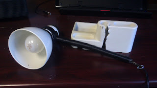
the sweet sounds of failure

pretty, but useless

Nothing!  Turns out the motor was completely under powered for the roughly 13 pounds I had loaded on it.  I have larger motors but the 25 tooth gear will never fit the motor shaft.  And the motor would be too large for the base.  Now I'm pissed.  I'm thinking I need a complete redesign, ridiculously over engineered and over powered.  But it will have to wait while I lick my wounds.