This should have been the easiest part of the build. The motor is designed to bolt right into a standard bicycle frame. However, I didn't choose a standard bicycle. The reason the Felt 1903 looks so cool is because of its unique styling. That unique styling means that nothing in the motor kit fits out of the box.
The motor mounts to the frame by two bolt-on clamps that attach to the seat tube and the down tube. There were two problems with mounting the motor in this frame. First, the front mount was too small to fit the large diameter of the down tube. Second, the spacing between the two frame tubes was too great for the motor, I needed spacers to bridge the gap. Spacers were included with the kit but they were too small. I needed to make my own. And the kit also came with alternative mounting brackets for large tube frames but they were completely jury rigged. I just couldn't use them, so I had to make a new front mount as well.
The front motor mount studs on the engine were placed too close together to clear the down tube. So the first step was moving the studs. I needed to fill the old bolt holes in the engine case and then drill and tap new holes spaced properly for my frame. I tried filling the holes with
Alumiweld but I guess I couldn't get the engine case hot enough. So instead I made some 10mm threaded aluminum rod on my lathe to fill the holes. Then I torqued the rod in the old bolt holes with some red Loctite. Now with the old bolt holes filled solid with aluminum, I could easily drill and tap the new holes partially on top of the old holes without any loss of strength.
 |
| threading aluminum rod |
 |
| studs secured in case |
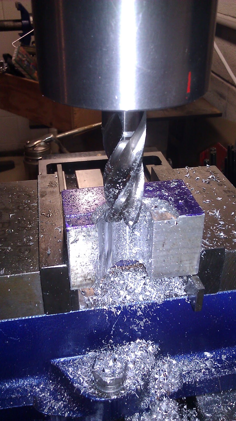
With the bolt holes for the front mount in the right location, I needed a new motor mount cap to fit the down tube. The radius on the old cap was just too small. So I started with another hunk of aluminum and squared it up in the mill. Then I rough cut the proper radius. I removed the machining marks in the radius with a sanding drum mounted in a pneumatic die grinder. After drilling some countersunk holes for the mounting bolts, I chamfered the edges on the mill and cleaned it all up in the blast cabinet.
 |
| milling the cap |
 |
| checking the fit |
 |
| Old cap vs. new. Overkill? |
With the mounts prepared, I still needed to make up about a 2.5" gap on each side of the motor. I thought of making the mounts out of aluminum but that would have taken a while. I considered making mounts out of HDPE plastic but it is really expensive. So I figured I would make the spacers out of hard rubber. But where could I find a large block of hard rubber? Harbor Freight to the rescue! I purchased a
solid rubber wheel chock from HF as my source of raw material.
 |
| wheel chock |
I used a hand saw to cut the block into a slab of the proper thickness. After carefully measuring and marking, I cut the mounts out on my scroll saw. I used brad point drills to drill perfect holes in the rubber for the mounting bolts. The edges were chamfered on my belt sander.
 |
| front spacer being but |
 |
| rear spacer in place |
The spacers and new mounts worked great. The motor is mounted solidly and the rubber helps to dampen vibrations. I had to order extra long 10 mm stainless socket head bolts for the mounts. I also placed a thin strip of rubber under the mounts to protect the paint.
 |
| front mount |
 |
| rear mount |


Where can i buy
ReplyDelete