
Part I - Intro
Part II - Lights & Locks
Part III - Marquee Paint
Time to rebuild the power supply. Every time I think I have the game working, it proves me wrong. The game will work for extended periods and then the screen will go red & black. And now it loses the sound as well when it does it. Best I can tell, all of the problems stem from the power supply.
 |
| power supply |
I know there is a bad connector, some questionable wiring, one resistor is burned out, the diodes look like they got hot, and the filter capacitors are probably bad. I could replace just the bad parts and hope for the best. However, the rest of the parts are so cheap, it makes sense just to replace everything.
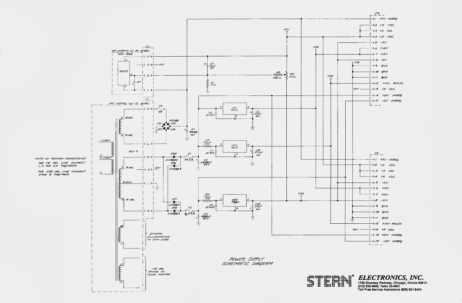 |
| power supply schematic |
Luckily the machine came with a complete set of paperwork, including schematics for every board. The service manual is available online, but I have never seen any of the schematics. I looked over the schematics and the board and made a list of parts. Good thing I did because for some reason, capacitor #3 (5V filter capacitor) is not listed on the schematic. I have since updated the schematic and added C3. Sourcing all of the parts was a pain, especially the 6800 µF and 15000 µF capacitors. I ended up ordering half of the parts from Newark Electronics and the other half from Great Plains Electronics. I probably could have ordered everything from Newark, but it is much easier to find things on the GP website and they had better prices on a few things.
 |
| the naked pcb and pile of old parts |
With the parts ordered, I began stripping the power supply. I removed everything except the potentiometer, fuse mounts, test points and output header pins. I used a solder sucker to remove the solder from the components. Then I just pushed the leads through with a hot soldering iron. With the board bare, I cleaned it with some circuit cleaner. I finished the prep by re-drilling all of the holes by hand to make sure the leads inserted with no problem.
 |
| burned circuit trace |
One of the header pins was badly burned; to the point that some of the copper traces were damaged. I scraped away as much of the burn as practical and soldered in a piece of solid wire to replace the damaged trace.
As I was removing the parts, I noticed that R5 was a 13Ω, 5W resistor. On the schematics it is listed as a 25Ω, 5W. This resistor goes to the input of the 7905 -5V regulator. So which part is correct? I asked for some advice on the All About Circuits forum. It looks like that resistor limits the amount of current that can flow through the 7905. The 25Ω resistor only lets about 0.5 amps through. Perhaps that was not enough current for the CPU board and someone swapped it out. I had already ordered the 25Ω resistor and didn't feel like paying the shipping just for one resistor. So I went to a local electronics supply shop and found a 15Ω resistor. That's close enough and should provide plenty of power to the CPU.
 |
| before |
 |
| after |
The parts arrived in a few days. Installing the new parts didn't take long. I mounted the resistors and diodes well above the surface of the board to hopefully help dissipate any heat. I increased the one burned out resistor from 1/4 W to 1/2 W. I finished by spraying some contact cleaner in the potentiometer and working it back and forth a few times.
With the board rebuilt, all that was left was to replace the contacts. The four and six pin plugs were so loose that touching them would make the screen go haywire. I decided to replace the standard contacts with Trifurcon contacts. They grip the pins on three sides instead of one and provide a much more secure connection. I replaced the contacts for all of the plugs on the power supply board. Even with the Trifurcon contacts, the four pin connector is still touchy. I will need to replace the plug and pins as well.
Time to re-install the board. I screwed the board down and attached the connectors. I powered up the power supply without plugging in the output connectors and adjusted the voltage to spec. Then I plugged in the output connectors and nervously hit the power switch. I watched for the magic blue smoke but all was calm. No smoke, but no game either. I checked the test points and all of the voltages were OK. I unplugged the CPU boards and quickly cleaned the contacts. I also found two resistors on the board that had their leads touching and may have been shorting out. I separated those, put the boards back in, powered up and voila! The game works.

Next I'll pull out the CPU boards and give those a good cleaning. A few decades of dust and corrosion can't be good for the game. Check back soon.
Parts List
Capacitors
22 µF, 35V x 4 $1.22
15000 µF, 16V $5.91
1000 µF, 35V $1.03
0.1 µF, 50V x 10 $0.32 (only 1 needed)
0.01 µF, 50V x 10 $0.27 (only 1 needed)
6800 µF, 35V $6.32
Diodes
1N4004G x 4 $0.76
6A4 x 4 $1.40
Resistors
12Ω, 500 mW x 10 $0.27 (only 1 needed)
5.6Ω, 5 W $0.35
25Ω, 5 W $0.35
Wiring
0.156" Header, 24 Pin x 4 $5.40 (only 1 needed)
Crimp Contact, 0.156", Trifurcon, 22-26AWG x 100 $8.00 (only xx needed)
Crimp Contact, 0.156", Trifurcon, 18-20AWG x 50 $4.00 (only xx needed)
Voltage Regulators
7905T $0.45
7815T $0.45
7812T $0.35
S&H + tax $10.99
Total $46.64 (price is actually higher than needed because I ordered extra of some parts)
No comments:
Post a Comment