Tuesday, November 26, 2013

QUADframe Boscam Mount

hexacopter camera mount

The hexacopter I am building will feature a Boscam FPV camera and pan/tilt mechanism.  The camera unit needed a solid yet lightweight mount for stability.  There was no room on the frame plates so I decided to mount the camera between two of the arms.  The carbon fiber tubes will provide a solid mounting platform and will also offer some protection for the camera system.

honeycomb carbon fiber

I needed a mounting plate to reach across two arms of the hexacopter.  It will be mounted to a boom block on each arm.  We had ordered some carbon fiber honeycomb sheet to play around with.  It is light and very stiff, perfect for the camera mount.  I made some rough measurements and got to work.

cut carbon fiber plate
If you do a web search on how to cut carbon fiber it is easy to get overwhelmed.  It is either as easy as cutting plywood or harder than herding cats and bad for your health to boot!  Turns out, it is super easy to get clean cuts in carbon fiber.  I had a cheap wet tile saw that I picked up for another project with a diamond blade.  I taped the cut line on the carbon fiber and cut it wet.  The tape prevents the carbon fibers from fraying.  The water keeps the cut cool so the resin doesn't melt and suppresses any dust that is bad to breathe and can short electronics.

I cut the plate to size on the tile saw.  The plates came out looking like factory cuts.  I laid out the boom blocks and mounting plate and carefully measured for the mounting holes.  I drilled the holes according to the blueprint below.  I finished the mount by rounding the sharp corners.

blueprint

finished mounting plate

One of the biggest complaints about the Boscam camera are the mounts.  Using anything other than the factory pan/tilt mount can be problematic.  Since I opted for the factory unit, mounting was easy.  I just used the pan/tilt as a template, centered it on the mount, and marked the holes.

Boscam pan/tilt mechanism

attached to frame

The final mount weighs just 28 grams, not including camera and pan/tilt mechanism.  It is rock solid, no flex or vibration.  The edges of the honeycomb plate look a little shaggy.  I need to dress them with some tape or glue to give it a more finished look.  Other than that, it almost looks like a factory piece.

Monday, November 25, 2013

Aluminum Pen

my aluminum Bic pen

I've got a thing for metal pens.  I've been planning on making my own but I haven't settled on a design yet.  So I have been collecting any decent metal pens that I can find.  Kickstarter is chock full of nice pen projects.  I've backed a few and been generally pleased.  One that I missed was the Baux Pen.  So simple, it's elegant.  It's nothing more than an aluminum tube machined to fit Bic pen parts.  Very cool idea.

the Baux Pen, my inspiration

Not too long ago, I posted about some landing gear I assembled for my hexacopter.  Turns out those landing legs weren't so great so I took them off and swapped them for a different design.  As I did that, I noticed the aluminum tubes on the bottom of the landing legs looked to be just the right diameter for a pen.  I checked with a Bic pen I had on hand and the outside diameters were almost identical.

drilling inside diameter

First I cut the tube to rough length.  Then I chucked the tube in my lathe and opened the inside diameter of the tip end with a letter G drill bit to a depth of 1/2".  Then I turned the tube around and parted off the other end to the correct length.  Drilled that end with a letter E drill bit.  The end plug is a bit more narrow than the tip.

parting off

Only thing left was to add a few grooves for a better grip and some visual appeal.  I used a 60 degree insert and spaced the end rings 0.020" apart and 0.010" deep.  At the tip I made the grooves 0.030" apart and 0.010" deep.  I was going to polish the tube but I really like the shine of the grooves against the bead blasted finish of the tube.

groovy

The Baux Pen must use tubing with a larger diameter than a Bic pen to achieve the step-down look at either end.  It gives the pen a much more interesting look than the straight sides of my pen.  But I used what I had on hand at the time.  Overall not bad for about 20 minutes work.  The metal body feels better than plastic and balances better when writing.  I may have to do this again in stainless steel.

QUADframe Sonar Mount


I am running the APM 2.6 autopilot on my hexacopter.  That system uses a sonar sensor to accurately measure altitude when flying close to the ground.  Mounting the sensor is somewhat critical.  It must have a clear view of the ground, be mounted away from any electrical wires which may cause interference, be clear of any mechanical interference from the props, and be isolated from vibration.

MaxBotix MB1240 Ultrasonic Rangefinder

The QUADframe that I am using does not come with a mount specifically for this sensor so I had to make my own.  I decided to mount the sensor on one of the landing legs.  I started by cutting a piece of aluminum angle to length.  I drilled two mounting holes in the mount and legs.  Then I scribed the contour of the leg into the aluminum.  I shaped the end of the mount on my belt sander to match the curve of the landing leg.

finished mount

sensor in mount

Next, I drilled the holes for the sensor.  I attached the sensor to the mount with nylon screws and standoffs to prevent shorts.  After that I added the wiring.  MaxBotix recommends making a power filter to eliminate electrical noise.  You simply add a 10 ohm resistor and 100 micro farad capacitor to the power supply lines.

power filter circuit

sensor wired up

I attached the senor to the APM according the the diagram below.


I added a piece of Kyosho Zeal between the mount and the landing leg to cut down on the vibration transferred to the sensor.  As a final measure, I wrapped the entire sensor in foam to cut down on acoustic interference.  The sensor appears to work pretty well.  It gives accurate readings when the hexacopter is static.  During flight the readings seem to get a bit erratic.  I may just need to adjust the sonar gain in the Mission Planner software.

ready to fly


Friday, November 22, 2013

Hideaway Book

You'll never find my stash!

I've always wanted a hideaway book.  I don't know why, it's probably not the best hiding place.  But it seemed like a fun project and a good use for an unwanted book.


I searched my bookcase and found an old dictionary.  The internet has pretty much made printed dictionaries obsolete, so why not do something useful with it.  I started by sealing all of the edges together with Mod Podge.  I weighed it down while it dried.

sealed the edges

Laid out the cut.
Then I started cutting.  At first, I used a hobby knife.  The cuts were nice and clean but it was taking forever.  So finally I got lazy and broke out my Fein Multimaster.  I used an E-Cut saw blade to slice through the pages.  The cuts weren't that clean (dull blade didn't help) but it was fast.

Started out nice and clean...

...finished ugly.  Hopefully, no one will ever see the inside ;-)

Once I had the book hollowed out, I vacuumed out the debris and sealed the edges with more Mod Podge. To hold the book closed, I used a pair of neodymium magnets.  I drilled a hole and epoxied one magnet in the hole and the other magnet to the cover.  The magnets are strong enough to hold lots of weight.

magnet set in pages

Back in the bookcase it goes.  Now if only I owned anything of value to put in it...

My secret is safe.

Laser Cut Company Emblem

Laser cut acrylic emblem

I am starting to make a few things to sell.  I want to brand the items with my company logo (They are mosquito claws, fyi).  Originally I wanted to have some hard enamel badges made.  The price per badge isn't too bad (about $2.50), but most places require minimum orders of 100 pieces; too much money.  I thought about just painting the logo on; but I decided a plastic 3D emblem would look much better.  The idea was to make a nice badge, much like what you would find on old radios.


company logo

I decided to use the laser cutting services from Ponoko.  The process is fairly simple.  Draw up your design in Inkscape.  Cut and paste the design into one of the Ponoko templates.  Adjust your line colors and weights to fit the Ponoko guidelines.  Then upload your design, choose the material, and order your parts. They have a large selection of materials to choose from.  I chose a bright red 0.118" thick acrylic sheet.

Ponoko template in Inkscape

Turnaround time was a bit slow.  It was 15 days before Ponoko even made my order.  It was a bit nerve wracking waiting as I had no idea how everything would turn out.  All that worry was for nothing as Ponoko delivered exactly what I expected.  To attach the emblems, I used heavy duty double sided tape for smooth surfaces or glue for rough surfaces or fabric.

Cut panel as delivered

I am very happy with the results.  The emblems look great on vintage electronics; exactly how I pictured it. The prices aren't too bad.  These cost me $35.46 including shipping.  I fit 49 pieces on one 7" x 7" sheet, so the cost per part was only $0.72.  Now that the design is on file, I can order more at any time in a multitude of colors.  It adds nothing to the function of my projects, but it does give things the professionally produced look I was going for.  I have plans to place another order for a slightly different design.  I'll post about them when they are made.

rebranded radio


Thursday, September 26, 2013

QUADframe/3DR uBlox GPS Mount

elevated GPS mount

The hexacopter I am building is based on the APM 2.6 flight control system.  That system uses a uBlox GPS module for autopilot capabilities.  Most professional multirotor helicopters have the GPS unit mounted on a rod above the airframe.  For ultimate accuracy the GPS unit must have an unobstructed view of the GPS satellites and be far from any electrical interference from the flight control system and motors; hence the elevated mounting.

Unfortunately, neither QUADframe nor 3D Robotics makes such a mount.  There are some kits on the market but I didn't feel like spending the money or waiting for shipping.  So I decided to make one.  I found some fiberglass rod that I salvaged from a broken umbrella; just the right diameter and stiffness.  I decided to use some rivet nuts to affix the rod to the frame plate and GPS housing.

GPS dissasembled and drilled for rivet nut

I disassembled the plastic GPS housing and used a 5/16" brad point bit to drill a hole in the base of the housing.  I had to drill the hole off center to avoid hitting any of the circuitry.

8-32 rivet nut installed in GPS case

I crimped the 8-32 rivet nut into place.

upper frame plate drilled for rivet nut

8-32 rivet nut installed

I did the same to the frame plate.  The location of the hole in the frame plate was dictated by the length of the GPS wires.  It needed to be relatively close the the APM unit.

fiberglass rod with thread

I settled on a 5" length for the rod.  I cut it to length with an abrasive wheel on my Dremel and threaded the ends of the rod to 8-32.  As expected, the threads didn't hold too well so I secured the rod in the inserts with epoxy.  Once it set, I reassembled the GPS module.

finished

Now the GPS unit is mounted well above any obstructions or interference.  I'll have to wait until everything is assembled until we know just how clean and accurate the GPS signal is.  Fingers crossed!

Sunday, September 15, 2013

Saw Blade Airgun Target

Saw blade target

The past few days I've been suffering from maker's block.  A project I've been working on has been getting the best of me.  I needed a quick and easy project to break out of my funk.  A few months ago I lent my chop saw to a friend who was installing a laminate floor.  When I got it back, the 12" blade was as sharp as a wet noodle.  Rather than throw it away, I decided to save it for a future project.  Good saw blades use high quality steel.  I figured this blade would make a great airgun target.

dull chop saw blade

I grabbed some of my favorite curb-side steel; old bed frames.  I used a cut-off wheel on my grinder to cut the pieces.  I cut the top piece 19" long and the vertical pieces 25" long; 20" for the height and 5" for the ground spike.  I screwed up and cut the spike on the right side on the wrong end of the piece, making the face frame uneven on that side.  I thought about scrapping that piece and making a new one, but it is only an aesthetic problem.  It will function just fine as is.

pieces cut

I welded the pieces together and dressed the welds and sharp edges with the grinder.  I drilled two holes spaced 10" apart on the top of the frame to support the blade.  I cut some old chain to length and bolted it to the blade and frame with 10-24 screws.  Luckily the blade already had expansion slots in it that fit the hardware perfectly.  Drilling through good saw blades is an exercise in futility without carbide bits.  I finished off the frame with a little spray paint over the bare spots.

welded together

weld detail

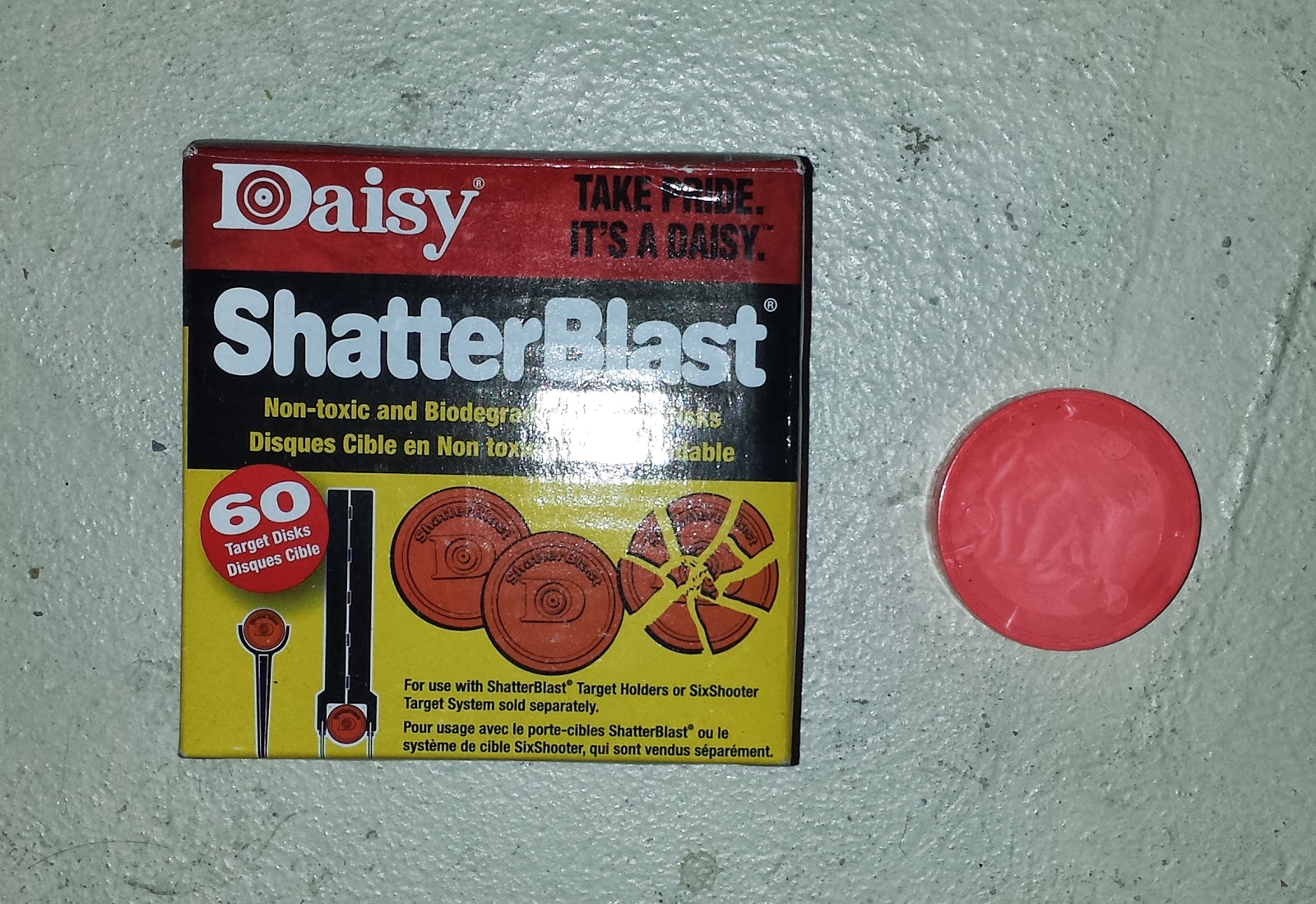
The blade has a tantalizing hole right in the center; perfect for a bullseye.  In the future, I think I will have to mount some sort of bell behind it.  As I don't have one right now, some Daisy ShatterBlast targets will have to suffice.  I was going to add some sort of mount for the Daisy targets on the back of the blade, but duct tape will work just as well.

targets for bullseye
The blade makes a nice sound when you hit it and the ShatterBlast discs make for a nice challenge at longer distances.  I think I may add a horizontal piece under the blade to serve as a stepping point to drive the spikes into the ground and prevent the legs from twisting.  But for now, it's time to shoot and have some fun.