Showing posts with label radio control. Show all posts

Sunday, March 2, 2014

Hexacopter Power Distribution Board

New PDB. It ain't pretty but it should work.

Recently my hexacopter crashed. Luckily I had a GoPro strapped to it and I saw one of the motors stop in flight. You can also hear a"pop" just before the failure.


After the crash I plugged the suspect motor into a good speed controller (ESC) and it worked fine.  So I plugged a good motor into the suspect ESC and it did not spin. Therefore, I concluded that the ESC had failed. I took the ESC apart to see which component failed but I couldn't find anything out of the ordinary.
But when I installed a new ESC, it didn't work either! After a little checking with my multimeter, I discovered that the positive terminal on the power distribution board (PDB) for that ESC was not getting power from the battery. Upon closer inspection, I could see that the circuit traces had burned out. This was a bit surprising considering that the board is rated for 90 amps and my motors should only be pulling around 45 amps max.

Note the 3 burned copper points around the lower right solder pad.

I had a few choices to fix it. Purchase the same thing again, purchase a different one, or make my own. I couldn't put the fate of my several thousand dollar hexacopter in the hands of the same component that failed once already. Other brands were an unknown and probably would not fit as well. I really liked the form factor of the original so I decided to make my own based on that design. I could etch my own PCB but I was concerned that it couldn't handle the power. So I decided to make a new PDB out of a piece of 0.025" copper plate. That's five times thicker than the original copper traces. It should have no problem handling the current.

I choose a piece of 0.093" polycarbonate to insulate the positive and negative sides. I marked and cut the plastic the same size as the original PCB. Then I cut out two pieces of copper plate larger than the plastic.


I glued the copper pieces to the plastic with 5 minute epoxy then trimmed the copper even with the plastic.

Each copper plate is almost as thick as the old PDB!

With that finished I drilled the mounting holes with a 1/8" drill.  I'll use nylon mounting screws to avoid any shorts. I followed by drilling a hole for the negative battery lead. The negative lead was passed through the bottom of the board and soldered to the top. I soldered a set of 3x6 header pins to the negative side of the board for the ESC receiver wires. All of the negative leads are wired together. The positive leads are separate. One positive lead is wired to the power supply wire for the flight control system. And the wiring harness from the old PDB was soldered to the signal wires.

Ready for ESC's
Finally, the six ESC's were soldered to the board. I covered the entire board in several coats of liquid electrical tape. Once it was dry, I screwed the new PDB to the center plate and attached the receiver leads. It fits the hexacopter exactly like the original. It is a little heavier, but this one can handle much more power. Now I just have to slap it back together and get her back in the air.


Ready for reassembly.

Tip: If you've never soldered to copper plate before, you need lots of flux and lots of heat. Coat the area to be soldered with flux. Heat it thoroughly with your soldering iron. Keep touching solder to the area until it melts. When it does, run your soldering iron in circles around the area to tin it with solder. Once you have a small layer of solder on, it will be much easier to solder your leads. Don't try to solder leads directly to bare copper plate.

Tuesday, November 26, 2013

QUADframe Battery Tray

battery tray on QUADframe Pro Six

One of the goals of our hexacopter is long flight times.  Our hex is large and relatively heavy (3.3 kg without batteries) so that requires large batteries.  We planned to fly with either three 6S 8,000 mAh batteries or two 6S 10,000 mAh batteries.  These batteries are large and heavy.  QUADframe sells a battery tray that mounts between the arms.  Unfortunately those mounts are designed for much smaller batteries.  Time to design a new battery mount.

QUADframe battery tray

After some playing around with the frame and batteries, I determined the best place to mount them was over the center plates of the frame.  I removed the protective dome and decided to mount the plate on the four standoffs that supported the dome.  I wanted to make the tray out of honeycomb carbon fiber.  Unfortunately I didn't have any left and I didn't want to wait to order it.  So I made my own carbon fiber laminate.  I epoxied some thin carbon fiber sheet I had to both sides of some good quality 1/8" plywood.  I clamped it in a vise between some boards as it dried.  The next day I cut it to size on a wet tile saw with a diamond blade.  Sorry, I forgot to take pictures as I made the laminate.

over-sized plate attached

Next I marked and drilled the holes to mount the tray.  The GPS mount that I made was in the way of the tray.  So I cut a groove in the tray for the GPS support.  Had I known the batteries were going there, I would have mounted the GPS somewhere else.  With that done I mounted the tray and tested the fit of the batteries.  The tray was longer than needed, so I cut it to the same width as the center plates of the frame.

screwed to standoff

To hold the batteries in place I used some heavy duty Velcro tape and Velcro straps.  I cut a slot in the tray to pass the straps through.  The standoffs were higher than needed so I cut about 1/2" off of each to bring the center of gravity down.

finished tray on frame

The tray is very strong; doesn't even budge with over 6 kg of batteries on it.  As a bonus, it also protects the flight control systems from crashes.  The 10,000 mAh batteries mount front to back, while the longer 8,000 mAh batteries mount lengthwise.

10,000 mAh batteries

8,000 mAh batteries
Even with all of that weight on top, the hex flies pretty well.  The 8,000 mAh setup balances slightly better because the third battery mounts below the hex on the landing gear (see first photo).  At some point in the future I may move the GPS mount so I can move the 10,000 mAh batteries closer to the center of the hex.  But for now, it works.


QUADframe Boscam Mount

hexacopter camera mount

The hexacopter I am building will feature a Boscam FPV camera and pan/tilt mechanism.  The camera unit needed a solid yet lightweight mount for stability.  There was no room on the frame plates so I decided to mount the camera between two of the arms.  The carbon fiber tubes will provide a solid mounting platform and will also offer some protection for the camera system.

honeycomb carbon fiber

I needed a mounting plate to reach across two arms of the hexacopter.  It will be mounted to a boom block on each arm.  We had ordered some carbon fiber honeycomb sheet to play around with.  It is light and very stiff, perfect for the camera mount.  I made some rough measurements and got to work.

cut carbon fiber plate
If you do a web search on how to cut carbon fiber it is easy to get overwhelmed.  It is either as easy as cutting plywood or harder than herding cats and bad for your health to boot!  Turns out, it is super easy to get clean cuts in carbon fiber.  I had a cheap wet tile saw that I picked up for another project with a diamond blade.  I taped the cut line on the carbon fiber and cut it wet.  The tape prevents the carbon fibers from fraying.  The water keeps the cut cool so the resin doesn't melt and suppresses any dust that is bad to breathe and can short electronics.

I cut the plate to size on the tile saw.  The plates came out looking like factory cuts.  I laid out the boom blocks and mounting plate and carefully measured for the mounting holes.  I drilled the holes according to the blueprint below.  I finished the mount by rounding the sharp corners.

blueprint

finished mounting plate

One of the biggest complaints about the Boscam camera are the mounts.  Using anything other than the factory pan/tilt mount can be problematic.  Since I opted for the factory unit, mounting was easy.  I just used the pan/tilt as a template, centered it on the mount, and marked the holes.

Boscam pan/tilt mechanism

attached to frame

The final mount weighs just 28 grams, not including camera and pan/tilt mechanism.  It is rock solid, no flex or vibration.  The edges of the honeycomb plate look a little shaggy.  I need to dress them with some tape or glue to give it a more finished look.  Other than that, it almost looks like a factory piece.

Monday, November 25, 2013

QUADframe Sonar Mount


I am running the APM 2.6 autopilot on my hexacopter.  That system uses a sonar sensor to accurately measure altitude when flying close to the ground.  Mounting the sensor is somewhat critical.  It must have a clear view of the ground, be mounted away from any electrical wires which may cause interference, be clear of any mechanical interference from the props, and be isolated from vibration.

MaxBotix MB1240 Ultrasonic Rangefinder

The QUADframe that I am using does not come with a mount specifically for this sensor so I had to make my own.  I decided to mount the sensor on one of the landing legs.  I started by cutting a piece of aluminum angle to length.  I drilled two mounting holes in the mount and legs.  Then I scribed the contour of the leg into the aluminum.  I shaped the end of the mount on my belt sander to match the curve of the landing leg.

finished mount

sensor in mount

Next, I drilled the holes for the sensor.  I attached the sensor to the mount with nylon screws and standoffs to prevent shorts.  After that I added the wiring.  MaxBotix recommends making a power filter to eliminate electrical noise.  You simply add a 10 ohm resistor and 100 micro farad capacitor to the power supply lines.

power filter circuit

sensor wired up

I attached the senor to the APM according the the diagram below.


I added a piece of Kyosho Zeal between the mount and the landing leg to cut down on the vibration transferred to the sensor.  As a final measure, I wrapped the entire sensor in foam to cut down on acoustic interference.  The sensor appears to work pretty well.  It gives accurate readings when the hexacopter is static.  During flight the readings seem to get a bit erratic.  I may just need to adjust the sonar gain in the Mission Planner software.

ready to fly


Thursday, September 26, 2013

QUADframe/3DR uBlox GPS Mount

elevated GPS mount

The hexacopter I am building is based on the APM 2.6 flight control system.  That system uses a uBlox GPS module for autopilot capabilities.  Most professional multirotor helicopters have the GPS unit mounted on a rod above the airframe.  For ultimate accuracy the GPS unit must have an unobstructed view of the GPS satellites and be far from any electrical interference from the flight control system and motors; hence the elevated mounting.

Unfortunately, neither QUADframe nor 3D Robotics makes such a mount.  There are some kits on the market but I didn't feel like spending the money or waiting for shipping.  So I decided to make one.  I found some fiberglass rod that I salvaged from a broken umbrella; just the right diameter and stiffness.  I decided to use some rivet nuts to affix the rod to the frame plate and GPS housing.

GPS dissasembled and drilled for rivet nut

I disassembled the plastic GPS housing and used a 5/16" brad point bit to drill a hole in the base of the housing.  I had to drill the hole off center to avoid hitting any of the circuitry.

8-32 rivet nut installed in GPS case

I crimped the 8-32 rivet nut into place.

upper frame plate drilled for rivet nut

8-32 rivet nut installed

I did the same to the frame plate.  The location of the hole in the frame plate was dictated by the length of the GPS wires.  It needed to be relatively close the the APM unit.

fiberglass rod with thread

I settled on a 5" length for the rod.  I cut it to length with an abrasive wheel on my Dremel and threaded the ends of the rod to 8-32.  As expected, the threads didn't hold too well so I secured the rod in the inserts with epoxy.  Once it set, I reassembled the GPS module.

finished

Now the GPS unit is mounted well above any obstructions or interference.  I'll have to wait until everything is assembled until we know just how clean and accurate the GPS signal is.  Fingers crossed!

Sunday, September 8, 2013

Mounting DJI 4114 Motors to QUADframe Mounts

DJI 4114 motor

We decided to use DJI 4114 motors from the S800 for our hexacopter.  They are low KV motors which means they will hopefully draw fewer amps and give us longer flight times.  Unfortunately they have an odd bolt hole pattern and do not fit on the QUADframe motor mounts.

bolt hole patterns do not match up

The DJI wires come out of the bottom of the motor and hit the mounting plate.  So first I had to make a clearance cut in the mounts for the wires.  I put two mounts into my milling vise at a time and located the center line.  I then used a 0.50" end mill to drill through the two mounts leaving a 0.25" deep semicircle on the end of each mount.  The mounts are made of G10 which machines easily.

cutting clearance for motor wires

The next step was measuring the hole pattern on the motor.  The holes are in a triangular pattern.  After much careful measuring, I came up with the pattern below.

DJI bolt hole pattern

I used the DJI motor mounts that came with the motor to locate the bottom hole.  I centered the DJI mount over the QUADframe mount and marked the bottom hole.  I then drilled the bottom hole in each of the QUADframe motor mounts with a #30 drill bit.  With that done, I centered the chuck over the bottom hole and used the X and Y dials to position the bit to drill the other two holes according to the above pattern.

compare original (L) to modified mount (R)

holy cow, it fits!

Luckily all of my measurements were correct and the QUADframe mounts fit the DJI motors on the first try. However, the captive nuts just barely hit the bottom of the DJI motors preventing them from sitting flush on the mount.

captive nuts hit base of motor

So I needed to remove some material from the base of the motors.  I used a grinding wheel in my Dremel to carefully grind small notches in the base where they hit the captive nuts.  I taped up the motors with painters tape first to keep the metal dust out of the motors.  When finished, I blew the motors out with some canned air just to be sure.

small notch ground into base of motor

With that problem solved it was time to mount the motors back on the frame, right?  Wrong.  One motor mount screw was directly under one of the boom blocks.  I had to cut a clearance notch in each boom block so it would sit flush over the screw.  And the other boom block pinched the wires so I had to file a notch in those as well.

clearance cuts on boom blocks

Finally everything fit.  I used a little thread lock on the motor screws and screwed the motors to the mounting plates.  The motors mounted nice and solid; almost a factory fit.  A more elegant solution would have been to machine new motor mounting plates, but I'm under a deadline and don't have the time.  However I expect I will have some carbon fiber mounting plates custom made at some point.

finally mounted

Thursday, September 5, 2013

LiPo Charging Station


The new hexacopter I am building will feature three 8000 mAh 6S Thunder Power batteries.  That's over $1,700 per set, and I plan on having two sets!  Now with that much capacity, my Accucel 6 would take forever to charge them.  And there is no way I am trusting $1,700 of batteries to a $23 charger.  Time to step up my charging game.  I figure Thunder Power must know how to charge their own batteries, so I selected their top of the line charger the 1430C.  It is capable of charging at a whopping 1000 watts!

Thunder Power 1430C

But to charge at that rate, you need a big power supply.  I chose the 1200 watt EFuel power supply.  It's good for 50 amps at 24 volts.  With that combination I should be able to charge a set of three batteries in parallel in about 30 minutes.

EFuel 1200 watt power supply

Now the charger and power supply are not delicate pieces of equipment.  But I would like to mount them inside a case for easy transport.  Also I would like to wire everything up once to reduce wear and tear on the connectors and minimize the chance of wiring something incorrectly.  I have this old equipment case that will fit everything nicely.  However am worried about the air circulation.  This stuff is likely to get very warm and I don't want to recirculate hot air into the equipment.  The best option is to mount everything onto a removable platform that will fit inside of the case for storage.

case for the charging system

I found an old street sign in my pile of materials.  I decided to bend it to fit the case.  The bent ends will serve as legs to allow for storage underneath the platform.  I tried to bend the sheet with my Harbor Freight bending brake.  I knew the brake wasn't rated for stock that thick but I figured I'd give it a try anyway.  Not a chance; the sheet wouldn't even budge.  So I clamped the sign to my steel bench and resorted to a 5 lbs mallet to "gently ease" it into shape.  Once bent to shape I trimmed the legs to bring the top to a height of 2 inches.

bad day to be a street sign

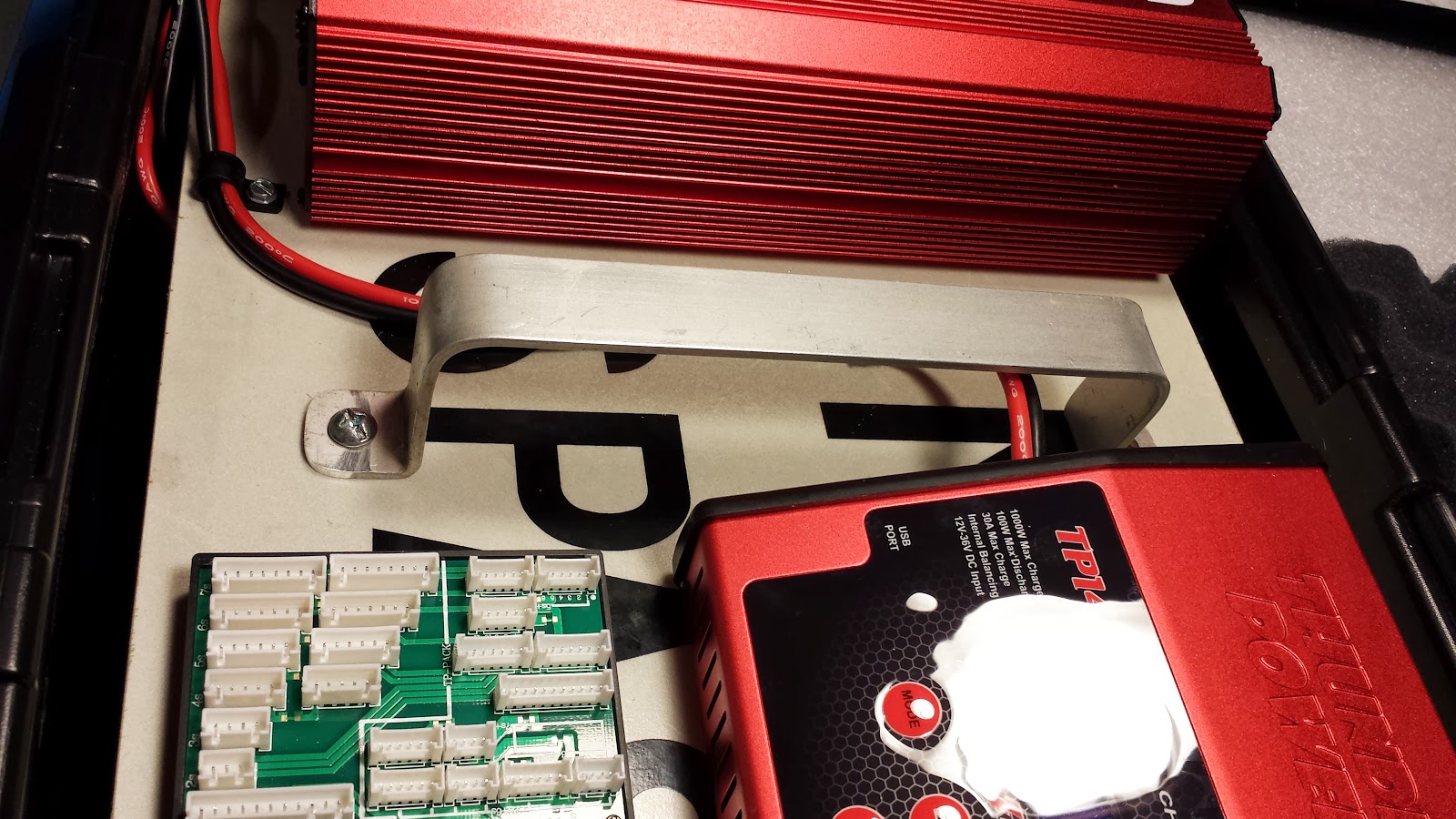
Next I disassembled the charger and power supply so I could punch mounting holes in them.  I guess I could have just zip tied them to the platform but I wanted a cleaner look than that.  I carefully chose the locations so that the screws would fit without touching any electrical contacts.  I then laid out the units on the platform, marked the mounting holes, and drilled the platform.

holes punched in bases

sign bent and ready to mount parts

Both units were held in place with 8-32 screws.  The power supply mounted easily.  I bolted down the base and then reassembled the unit.  The charger was a little more difficult.  Because the sides of the unit also act as the feet, I couldn't tighten down the charger until the unit was first reassembled.  So I put toothed lock washers under the screw heads so that I could tighten the nuts without access to the screw heads.

PSU and charger mounted to base
I decided to add a handle to make it easier to remove from the case.  I found a piece of aluminum bar and hand-bent it into shape in a vise.  The middle was sagging a little from the weight so screwed the handle into wooden blocks underneath the base.

handle

wooden blocks for support

Next I needed to wire the charger to the power supply.  I could have just inserted the banana plugs into the binding posts.  But I wanted something a bit more permanent.  So I soldered some gold plated ring terminals to the charger wires and clamped them down in the binding posts.  Then I secured the wires to the base with cable clamps.  No need to worry about the wires coming out or someone hooking things up incorrectly.

ring terminals for binding posts

The charging system fits perfectly in the case.  Now it is nice and easy to transport which helps considering the system is pretty heavy.  A premium storage solution for a premium charging system.  I feel much better now knowing this $430 system is properly protected.

completed charging system