Saturday, January 18, 2014

Astro Invaders Arcade Restoration - Marquee Touch-Up


Part I - Intro
Part II - Lights & Locks

In a previous post I repaired my marquee light. With the light shining through, the missing paint was now much more noticeable. Actually, it's not paint. I believe it was screen printed. Over the years the ink had dried out and was starting to crack. In some of the worst spots, it was flaking off. So I decided at the very least, I should preserve the sign in its current condition. With any luck, I might even be able to make it look a little better.

flaking ink

I started by cleaning the back of the marquee. Years of dust had accumulated over the ink and was probably muddying some of the colors. Because of the compromised condition of the ink, I couldn't simply scrub the sign clean. So I sprayed the marquee with Fantastik and let it soak for a minute. Then I rinsed it under a very light stream of water. That removed much of the grime. I followed by very lightly wiping the ink with a damp paper towel. That did pull off a few flakes of ink from the worst area but it got the rest of the marquee much cleaner.
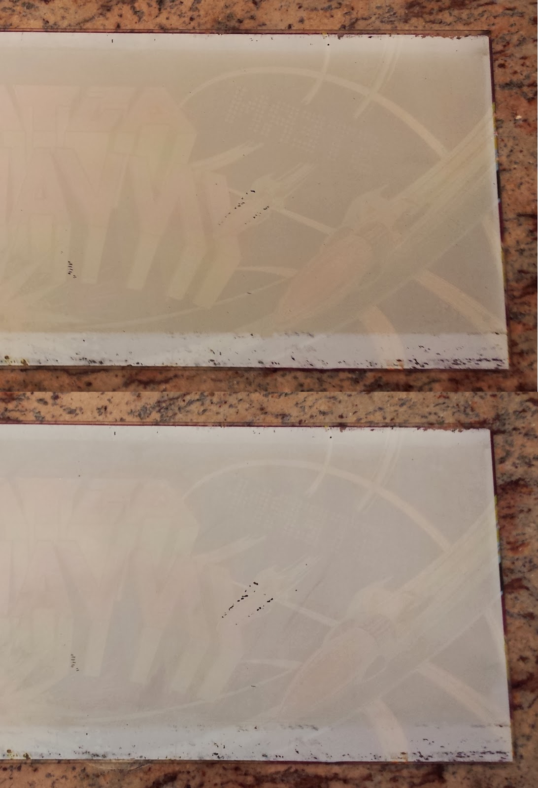
Before (top) & After (bottom)

With the sign sufficiently clean I needed to protect the ink so that it wouldn't crack or flake anymore. I read on a forum that Krylon Triple-Thick Crystal Clear Glaze is the best option for preserving old pinball marquees and backglass. I found a can at Michaels and applied it per label directions over the ink; two heavy coats. The glaze dried clear and left a nice thick protective coating. Now I don't have to worry about the marquee getting any worse. More importantly, I could try and repair the missing ink on the sign without fear of ruining the sign. Any mistakes could be wiped away.


If you read the arcade/pinball forums, you will find most people advise against repainting translucent marquees.  Even if you match the colors perfectly, the translucency will likely differ and your repair might actually be more obvious than the damage was. While trying to decide what to do, I came across a 24 pack of Sharpie markers at home. For some reason I thought they might be suitable for repairing the marquee art. I tried them along the edges of the marquee, hidden by the brackets. The colors ended up being too transparent; even with multiple coats.

So next I decided to try fine point Sharpie oil-based paint pens. I picked up a few colors that were close to the marquee colors and tried them out along the hidden edges of the sign. I tried two colors to touch up the purple area of the marquee. The colors weren't an exact match but the repair looked OK...until I put it up to the light.

repair lighted from the front

same repair lighted from behind

With the light shining through the marquee, any spot of paint that was over the original ink made the area more opaque and painfully obvious. IF I could get paint that was a closer match, and IF I could get the paint ONLY on the clear areas without getting ANY paint on the ink, the repairs might be OK. But those are a lot of ifs.

Luckily, the black paint is completely opaque. Repairs made with the black paint pen were completely invisible. The area of the marquee with the worst flaking is actually black and light blue. If I can at least touch up the black, the missing light blue might not be that noticeable. So I carefully went to work with with a black extra-fine point Sharpie paint pen.

before (top) & after (bottom)

The resulting repair isn't perfect, but it looks pretty good. I've got two things going for me. Most of the flaking paint is light blue which blends well with the clear areas. And the worst part is in the area of an explosion. So the bits of flaked and missing paint almost look intentional. This will do for now. Maybe in the future I will play with those light blue areas again. The final step in the touch-up will be polishing the front of the marquee with some Novus plastic polish. But that will wait until the rest of the cabinet is finished.

back on the arcade

The difference is subtle. From 5 feet away, nobody would probably notice the difference. But it is certainly better than it was. And most importantly, the marquee will be protected for the next three decades. Next up, I'll rebuild the power supply.

Krylon glaze      4.49
Paint pen           2.50
Total              $6.99

Sunday, January 5, 2014

Astro Invaders Arcade Restoration - Locks & Lights


In Part I I got my Astro Invaders arcade working again.  Now I want to fix the lights and locks.  The lights don't affect the function of the game, but they sure do make it look better.  And while the locks don't sound too important, it is a real pain having the coin door flopping around and the back constantly falling off.  Also, there are safety switches on the back and coin door that shut off the game if they are open.  So without the locks, they must be taped down.

The locks were an easy fix.  I ran down to Home Depot and picked up a 5/8" cam lock for the coin door and a 7/8" cam lock for the back.  Both screwed right in and the included hardware fit without any trouble.  I tried to find matching keys but didn't have any luck.  Eventually I may re-pin one of the locks so one key will fit both.  But this will do for now.

coin door lock
back lock

Next up were the coin door lights.  There are two #44 bulbs on the coin door.  I purchased replacement bulbs at Radio Shack.  Once installed, I bent the metal mounting tabs a bit to center the bulbs.

new bulbs

all lit up

Lastly, but most importantly was the marquee light.  Astro Invaders has some great artwork and I really want it to stand out.  So I opened up the marquee and checked the light.  The F14T12 fluorescent bulb was clearly burned out, so I purchased a new one.  While I was at it, I purchased a pack of new starters too. The light sockets were not attached to the brackets so I screwed them back on with some 4-40 screws.  Then I installed the new bulb and starter, flipped the power switch, and...  The light flickered for a split second and went out. Oh well.  I should have known something would give me trouble.

original light fixture

Time to troubleshoot.  I checked the fuse; that was good.  I checked the AC voltage in; that was fine.  I figured the ballast must be bad.  Back to Home Depot for a replacement.  I could have purchased this direct replacement for less money.  But I miscounted the wires on the original ballast and thought it wouldn't work. So instead I picked up a GE GEM120TC120/2-DIY ballast.  It is basically the same thing, but it eliminates the starter. One less thing to go wrong in the future.  Wiring it in was relatively easy.  See the picture for details.  I left the original fuse in place.  I used wire nuts in case the ballast needs to be replaced in the future. Finally I dated the ballast and light so I (or some future tech) will know when they were last replaced.

new ballast wired in

wiring diagram for new ballast

Just for reference, here is how the old ballast was wired in.

original wiring

With the new ballast in place it was time to see if my hard work had paid off.  I flipped the switch and the light came on.  Hurray!  It's starting to look like an arcade again.  In the next installment, I think I will start cleaning all of the circuits, switches, and connectors.   Check back.

gotta love that artwork!

I don't usually do this (because I don't want to know) but I think I'll keep a running total on what I spent on this project.  Here's what this part cost.

Starter                   1.97
5/8" cam lock        4.59
7/8" cam lock        4.92
Ballast                 11.99
Fluorescent bulb  10.72
#44 Lamps           0.99
Tax                      2.46
Total                $37.64

Saturday, January 4, 2014

Astro Invaders Arcade Restoration


A friend gave me a few arcade games. One of them is Astro Invaders.  I was told that the machine used to work sporadically, sometimes requiring a whack to the side to get it to work.  Now it just has these red and black vertical bars and repeats this incredibly annoying "pew, pew, pew..." sound over and over.  When I pound the side of the cabinet, the screen flashes and there is an explosion sound.  Then it goes back to the red and black screen.  I was going to sell it as-is, but I decided to restore it instead.  If I decide to sell it later, I can probably double my money if the game works.  I've never worked on an arcade before so this will be a good learning experience.

screen problems

Luckily the game included all of the manuals and schematics.  I read over that material to see if it said anything about this red screen.  No luck.  So I opened up the back of the cabinet and identified all of the sections of the game.  I noticed that the power supply board was hanging loose in the cabinet.  I grabbed four 6-32 screws and secured the power supply board to its mounts.

power supply board

Next came some step-by-step troubleshooting.  I started with the power supply as that is the first section of the game.  First I checked the fuses.  I used my multimeter to check for continuity.  All of the fuses were good.  However, I did notice that one of the fuses was loose in the mount.  I removed the fuse, pinched the mount together, and reinstalled the fuse.  The game still didn't work, but now when I whack the side of the cabinet nothing happens.  Looks like the loose board and/or fuse was causing things to short out.

To see if the power supply was working, I checked the voltage test points (labeled "TP") on the circuit board.  The manual and the board tell you what voltages to expect at the test points.  I checked TP1.  It should be between 5.3 and 5.6 volts.  It measured less than 2 volts.  So I adjusted the small potentiometer next to the test point until my meter read 5.3 volts.  Suddenly the repeating noise stopped.  I peaked around the front of the cabinet and behold!  The game was working.  I played for one life.  But when my ship was destroyed, the game crashed and went to a blue screen.  So I checked the other test points.  The 12 and 15 volt test points were way off (< 3 volts).

A few hours later I powered up again and checked the voltage directly at the voltage regulators.  The voltages were all as expected, about 11.8v from the 7812 and 14.9v from the 7815.  I checked the test points again and they were all within spec.  I played the game and everything worked perfectly.  Hmmm? As happy as I was that it worked, I need to know why it wasn't working before.  Otherwise, it might happen again.  And it did.  Every once in a while I would get the same screen problem.  Eventually, I traced the problem to a loose wire connector on the power supply board that came from the SG323 regulator (upper left corner of the power supply in the above picture).  I twisted the connector around until it worked again but it will need to be replaced when I get deeper into the restoration.

It's alive!

Well that was a bit frustrating but relatively easy.  Next, I'll fix the lights and locks.  Stay tuned.

Friday, December 20, 2013

Hammerli 850 Cheek Rest

elevated cheek rest

Lately I've been busy improving my Hammerli 850 air rifle.  With the new trigger job, this rifle is quickly becoming one of my favorites.  The next problem to tackle is the height of the cheekpiece on the stock.  It is too low for my scope.  For best accuracy your cheek should be pressed firmly against the stock with your eye perfectly centered in the eyepiece.  To see through my scope, I must lift my cheek off of the stock.  Not comfortable and bad for accuracy.  Good target stocks will have an adjustable cheek piece.  If this were a wooden stock, I could just cut it and install a mechanism to raise it.  Not so easy with a hollow plastic stock; so I decided to make a new cheek rest.

kydex formed to stock

I purchased a sheet of kydex  from Amazon.  I went with a thick piece (0.118") for the extra strength.  Next I cut the kydex sheet in half (6" x 12") with a pair of sheet metal shears.  Then I preheated the oven to 350 degrees and placed the kydex in a Pyrex dish for three minutes.  I checked the sheet with a spatula to make sure it was very pliable.  Then I scooped it up and placed it on the stock folding it over the cheek piece with gloved hands.  I quickly got the alignment just right and held the kydex tight against the stock as it cooled.  In about 5 minutes the kydex had cooled and was rigid.  It formed perfectly to the shape of the stock and the pattern and color even matched the stock.

tracing the pattern

To make a pattern, I wrapped a piece of paper over the stock.  Then I traced the edges of the cheek swell with a scrap of aluminum sheet.  The aluminum worked really well, cleanly marking only the edge.  I carefully cut the pattern out with an x-acto knife.  I placed it back on the stock and drew some witness marks on the paper and stock so I could lines things up later.  Finally, I cut the pattern in half.

spacer taped to stock

The next step was finding the correct height for the new cheek rest.  I experimented by placing pieces of rod under the cheek rest until my eye was perfectly aligned with the scope.  Turns out a 1" rod and a Bic pen tube provided the perfect height (1.319").  I taped the spacer to the stock and put the kydex over it to test.  Perfect.  Now to make the bottom of the new cheek rest match the contour of the stock.  I coated the back of the pattern pieces with spray glue.  Then using the witness marks, I lined each pattern up on the stock and stuck them to the kydex.

hlaf of pattern glued to kydex

The bulk the excess kydex was trimmed away with the metal shears.  Then the kydex was formed exactly to the pattern on the belt sander.  Now to attach the new cheek rest to the stock.  I was going to make the cheek rest adjustable by cutting slots in the kydex but why bother?  I only needed to set it correctly one time.  And most adjustable cheek rests have large ugly knobs on one side to tighten the bolts.  I wanted a cleaner look.  So I carefully laid out the position of the screws and drilled two 3/32" pilot holes through the kydex and into the stock on each side.  I then opened up the holes on the kydex to 13/64" and countersunk them so the screws would sit flush.  I enlarged the holes in the stock to #25 and tapped them for 10-24 screws.  Although the stock is hollow, it is thick enough where the cheek rest is providing plenty of threads.

screw holes in kydex

The pattern peeled off the kydex rather easily and I cleaned up any residual glue with Goo Gone.  I cleaned up any uneven spots on the belt sander and dressed the edges with 220 grit sandpaper.  Finally I screwed the new cheek rest to the stock with stainless flat head socket cap screws.  I was going to back up the screws with nuts but the plastic held the screws tight.  I added a drop of thread lock to each screw just to be sure.

finished and installed

height relative to scope

The new cheek rest is great.  It looks like a factory accessory and is rock solid.  Now that I don't have to move my head around looking for the eyepiece, I can get on target much faster.

PS - If you are cutting kydex on a scroll saw, I found that a 15 tpi blade at 500 rpm gave a very clean cut.  No melting and minimal saw marks.

Thursday, December 19, 2013

Paracord Cobra Bracelet

cobra pattern paracord bracelet

After making my paracord pouch, I realized that my 9 year old daughter would really enjoy making things with paracord.  I figured a bracelet would be the perfect beginner project.  Easy to do and what young girl doesn't love bracelets?  So I picked out some colors of paracord that I thought she would like and some small buckles at Michaels.  I showed her the first weave and then she took over.  In no time she was weaving the paracord like a pro.  Here's how we did it.


First cut 4 feet of each color of cord.  Then fuse the two pieces of cord together by melting the ends.


Loop one end through one of the buckles.


String the cord through the other buckle and wrap the cords around your wrist to measure.  Tie the buckle to the cords with overhand knots.


Ready to weave.

She wanted purple down the middle with pink lines down the sides.  Whatever color you want down the middle is the color you start with each time.


The purple cord is laid across the bracelet.


The pink cord goes over the purple, behind the bracelet, and through the loop from the back.


Pull the cords tight.


after several passes
Continue, repeating the same sequence each time.  Purple over the front of the bracelet, pink under the bracelet.


Repeat until you reach the other buckle.


To finish just trim the ends leaving about 1/8".  Then melt the ends with a lighter and use the metal part of the lighter to push the melted cord against the bracelet.  This mushrooms the end of the cord and melts it to the surrounding cord so that it can't pull through.  That's it.  Enjoy your new bracelet.

Saturday, December 14, 2013

Paracord Pouch

finished pouch holding 3/8" steel shot

Now that I have made a paracord needle, it's time to put it to use.  These slingshot ammo pouches were what first inspired me to try some paracord projects.  A quick search on the web turned up this set of plans for a paracord pouch.  It is a slightly different design than the Simple Shot pouches but it should work.

Start with 30 feet of paracord.  Use a rubber band or tape to secure one end of paracord to can.  Also secure a sharpie to can to add slack to line.  (I used a pen but found it a bit tight afterwards.  The sharpie will give more slack.)  Wrap the cord around a soda can 25 times and remove the sharpie.

25 wraps of paracord

Add your needle to the end of the paracord and weave it up through the wraps by twos.  Start by going under the first two wraps.  Continue spacing each line about 1/2" apart.  Don't worry too much about spacing, just push the lines together, you can feel when they are close enough.

starting to weave

and more

Make sure to work any twists and kinks out of the paracord as you go.  Your last weave should go down and thread back under the bottom wrap.

last weave

Now it is time to start on the bottom.  Push everything down even with the bottom of the can.  The bottom is constructed by making half hitches around the bottom of the weave.  Alternate the half hitches through the horizontal wraps and through the base of the vertical weaves.

starting first half hitch

finishing first half hitch

first row of half hitches complete

Continue the half hitches around the base of the can.  Keep the hitches tight so you have a solid base.  As you get towards the center you have to skip some half hitches and maybe go every other one.  Otherwise you end up making the base cone-shaped rather than flat.  If there is an exact formula for this, I'm not aware of it.  The center gets a little tricky and I just went by feel, adding half hitches where it looked like I needed one.

completed base

Now remove the pouch from the can.  To finish the base, I passed the working end inside the pouch.  Then I secured it to the base with an overhand knot and cut off the excess.  I inverted the pouch and finished it off by melting the knot together, permanently securing it.

inside view of melted knot

The starting end of the cord is then woven back down the side of the pouch next to one of the other vertical lines.  Melt that end and press it to the adjacent line, fusing them together.  Take the extra cord (or cut a new piece) and weave it around the top to create a drawstring (see first picture).  Add a cord lock then knot, trim, and melt the ends of the drawstring.  All done!  Add your favorite junk and pull it closed.

finished pouch