Monday, January 20, 2014

Astro Invaders Arcade Restoration - Circuit Board Cleaning


Part I - Intro
Part II - Lights & Locks
Part III - Marquee Paint
Part IV - Power Supply Rebuild

circuit boards in "card cage"

Now that the game is working, I want to make sure it is working as well as it possibly can. Decades of dust and corrosion on the circuit boards, pots, and IC pins can lead to sub-optimal performance. I'm not sure if it will help, but it certainly can't hurt to give everything a good cleaning.

(L to R) video, CPU, & sound boards

I started by pulling out the card cage containing all of the circuit boards. I sprayed each with circuit cleaner and scrubbed them with a soft toothbrush.  Any IC's that could be removed were worked back and forth in the sockets to clean the pins. There are 8 exposed potentiometers on the sound board. One is the master volume and then I believe each game sound has it's own volume control. I marked the position of each one with a silver Sharpie before cleaning . Then they were sprayed with contact cleaner/lube and worked back and forth. I found a capacitor and resistor whose leads were touching and perhaps causing problems. I corrected that and checked for the same problem on the rest of the components. I finished up by cleaning the board contacts with 0000 steel wool. As I worked I looked closely for any signs of failing components. Everything looked good. I blew the boards dry with compressed air, cleaned the card cage and put it all back together.

someone didn't want to find an adapter for the ground plug

cracked power cord

While I was at it, I changed the power cord. The ground pin was broken off of the plug and the cord was starting to crack. I was going to pick up some 3 lead cable and make my own power cord. But buying wire by the foot is expensive. So instead I purchased an extension cord. With the plug molded in, the cord looks more professional anyway.


I kept the cord 11 feet long, like the original. I just cut off the female end and wired the cord to the connector with some new female crimp terminals. I kept the original warning card in place and added a zip-tie as a strain relief. The new power cord is much heavier duty than the original. In fact, if I were doing it again, I would probably go with 16 gauge wire. It was hard getting the 14 gauge wire into the connector. But this will stand up to years of hard use.

new cord in place

Luckily the game still works and it seems like the sound is less scratchy than before. The game also used to have a few errant pixels lit up on the screen during game play. That seems to be gone as well. Next up I'll pull out the control panel and restore that.


PS - I didn't even waste the cut portion of the extension cord.


Extension Cord   $15.96

Saturday, January 18, 2014

Astro Invaders Arcade Restoration - Power Supply Rebuild


Part I - Intro
Part II - Lights & Locks
Part III - Marquee Paint


Time to rebuild the power supply. Every time I think I have the game working, it proves me wrong. The game will work for extended periods and then the screen will go red & black. And now it loses the sound as well when it does it. Best I can tell, all of the problems stem from the power supply.

power supply

I know there is a bad connector, some questionable wiring, one resistor is burned out, the diodes look like they got hot, and the filter capacitors are probably bad. I could replace just the bad parts and hope for the best.  However, the rest of the parts are so cheap, it makes sense just to replace everything.

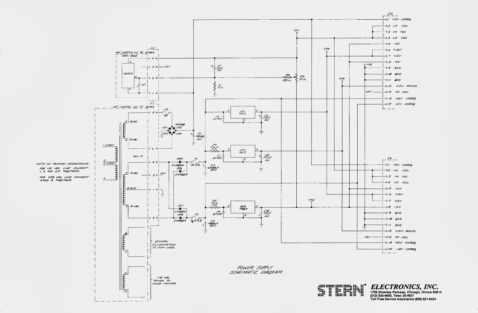
power supply schematic

Luckily the machine came with a complete set of paperwork, including schematics for every board. The service manual is available online, but I have never seen any of the schematics. I looked over the schematics and the board and made a list of parts. Good thing I did because for some reason, capacitor #3 (5V filter capacitor) is not listed on the schematic. I have since updated the schematic and added C3. Sourcing all of the parts was a pain, especially the 6800 µF and 15000 µF capacitors. I ended up ordering half of the parts from Newark Electronics and the other half from Great Plains Electronics. I probably could have ordered everything from Newark, but it is much easier to find things on the GP website and they had better prices on a few things.

the naked pcb and pile of old parts

With the parts ordered, I began stripping the power supply. I removed everything except the potentiometer, fuse mounts, test points and output header pins. I used a solder sucker to remove the solder from the components. Then I just pushed the leads through with a hot soldering iron. With the board bare, I cleaned it with some circuit cleaner. I finished the prep by re-drilling all of the holes by hand to make sure the leads inserted with no problem.

burned circuit trace

One of the header pins was badly burned; to the point that some of the copper traces were damaged. I scraped away as much of the burn as practical and soldered in a piece of solid wire to replace the damaged trace.

As I was removing the parts, I noticed that R5 was a 13Ω, 5W resistor. On the schematics it is listed as a 25Ω, 5W. This resistor goes to the input of the 7905 -5V regulator. So which part is correct? I asked for some advice on the All About Circuits forum. It looks like that resistor limits the amount of current that can flow through the 7905. The 25Ω resistor only lets about 0.5 amps through. Perhaps that was not enough current for the CPU board and someone swapped it out. I had already ordered the 25Ω resistor and didn't feel like paying the shipping just for one resistor. So I went to a local electronics supply shop and found a 15Ω resistor. That's close enough and should provide plenty of power to the CPU.

before

after

The parts arrived in a few days. Installing the new parts didn't take long. I mounted the resistors and diodes well above the surface of the board to hopefully help dissipate any heat. I increased the one burned out resistor from 1/4 W to 1/2 W. I finished by spraying some contact cleaner in the potentiometer and working it back and forth a few times.

With the board rebuilt, all that was left was to replace the contacts. The four and six pin plugs were so loose that touching them would make the screen go haywire. I decided to replace the standard contacts with Trifurcon contacts. They grip the pins on three sides instead of one and provide a much more secure connection. I replaced the contacts for all of the plugs on the power supply board. Even with the Trifurcon contacts, the four pin connector is still touchy. I will need to replace the plug and pins as well.

Time to re-install the board. I screwed the board down and attached the connectors. I powered up the power supply without plugging in the output connectors and adjusted the voltage to spec. Then I plugged in the output connectors and nervously hit the power switch. I watched for the magic blue smoke but all was calm. No smoke, but no game either. I checked the test points and all of the voltages were OK. I unplugged the CPU boards and quickly cleaned the contacts. I also found two resistors on the board that had their leads touching and may have been shorting out. I separated those, put the boards back in, powered up and voila! The game works.


Next I'll pull out the CPU boards and give those a good cleaning. A few decades of dust and corrosion can't be good for the game. Check back soon.


Parts List

Capacitors
22 µF, 35V x 4       $1.22
15000 µF, 16V       $5.91
1000 µF, 35V         $1.03
0.1 µF, 50V x 10    $0.32 (only 1 needed)
0.01 µF, 50V x 10  $0.27 (only 1 needed)
6800 µF, 35V         $6.32

Diodes
1N4004G x 4     $0.76
6A4 x 4              $1.40

Resistors
12Ω, 500 mW x 10    $0.27 (only 1 needed)
5.6Ω, 5 W                  $0.35
25Ω, 5 W                   $0.35

Wiring
0.156" Header, 24 Pin x 4                                            $5.40 (only 1 needed)
Crimp Contact, 0.156", Trifurcon, 22-26AWG x 100   $8.00 (only xx needed)
Crimp Contact, 0.156", Trifurcon, 18-20AWG x 50     $4.00 (only xx needed)

Voltage Regulators
7905T    $0.45
7815T    $0.45
7812T    $0.35


S&H + tax  $10.99
Total  $46.64 (price is actually higher than needed because I ordered extra of some parts)


Astro Invaders Arcade Restoration - Marquee Touch-Up


Part I - Intro
Part II - Lights & Locks

In a previous post I repaired my marquee light. With the light shining through, the missing paint was now much more noticeable. Actually, it's not paint. I believe it was screen printed. Over the years the ink had dried out and was starting to crack. In some of the worst spots, it was flaking off. So I decided at the very least, I should preserve the sign in its current condition. With any luck, I might even be able to make it look a little better.

flaking ink

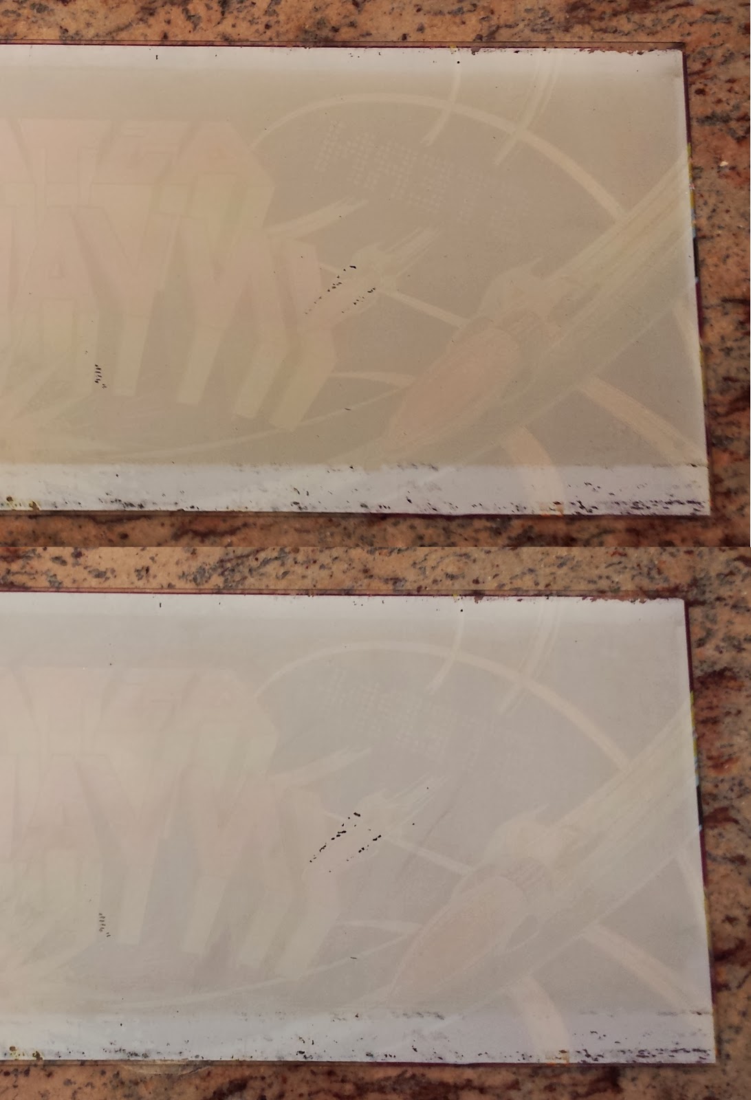
I started by cleaning the back of the marquee. Years of dust had accumulated over the ink and was probably muddying some of the colors. Because of the compromised condition of the ink, I couldn't simply scrub the sign clean. So I sprayed the marquee with Fantastik and let it soak for a minute. Then I rinsed it under a very light stream of water. That removed much of the grime. I followed by very lightly wiping the ink with a damp paper towel. That did pull off a few flakes of ink from the worst area but it got the rest of the marquee much cleaner.

Before (top) & After (bottom)

With the sign sufficiently clean I needed to protect the ink so that it wouldn't crack or flake anymore. I read on a forum that Krylon Triple-Thick Crystal Clear Glaze is the best option for preserving old pinball marquees and backglass. I found a can at Michaels and applied it per label directions over the ink; two heavy coats. The glaze dried clear and left a nice thick protective coating. Now I don't have to worry about the marquee getting any worse. More importantly, I could try and repair the missing ink on the sign without fear of ruining the sign. Any mistakes could be wiped away.


If you read the arcade/pinball forums, you will find most people advise against repainting translucent marquees.  Even if you match the colors perfectly, the translucency will likely differ and your repair might actually be more obvious than the damage was. While trying to decide what to do, I came across a 24 pack of Sharpie markers at home. For some reason I thought they might be suitable for repairing the marquee art. I tried them along the edges of the marquee, hidden by the brackets. The colors ended up being too transparent; even with multiple coats.

So next I decided to try fine point Sharpie oil-based paint pens. I picked up a few colors that were close to the marquee colors and tried them out along the hidden edges of the sign. I tried two colors to touch up the purple area of the marquee. The colors weren't an exact match but the repair looked OK...until I put it up to the light.

repair lighted from the front

same repair lighted from behind

With the light shining through the marquee, any spot of paint that was over the original ink made the area more opaque and painfully obvious. IF I could get paint that was a closer match, and IF I could get the paint ONLY on the clear areas without getting ANY paint on the ink, the repairs might be OK. But those are a lot of ifs.

Luckily, the black paint is completely opaque. Repairs made with the black paint pen were completely invisible. The area of the marquee with the worst flaking is actually black and light blue. If I can at least touch up the black, the missing light blue might not be that noticeable. So I carefully went to work with with a black extra-fine point Sharpie paint pen.

before (top) & after (bottom)

The resulting repair isn't perfect, but it looks pretty good. I've got two things going for me. Most of the flaking paint is light blue which blends well with the clear areas. And the worst part is in the area of an explosion. So the bits of flaked and missing paint almost look intentional. This will do for now. Maybe in the future I will play with those light blue areas again. The final step in the touch-up will be polishing the front of the marquee with some Novus plastic polish. But that will wait until the rest of the cabinet is finished.

back on the arcade

The difference is subtle. From 5 feet away, nobody would probably notice the difference. But it is certainly better than it was. And most importantly, the marquee will be protected for the next three decades. Next up, I'll rebuild the power supply.

Krylon glaze      4.49
Paint pen           2.50
Total              $6.99

Sunday, January 5, 2014

Astro Invaders Arcade Restoration - Locks & Lights


In Part I I got my Astro Invaders arcade working again.  Now I want to fix the lights and locks.  The lights don't affect the function of the game, but they sure do make it look better.  And while the locks don't sound too important, it is a real pain having the coin door flopping around and the back constantly falling off.  Also, there are safety switches on the back and coin door that shut off the game if they are open.  So without the locks, they must be taped down.

The locks were an easy fix.  I ran down to Home Depot and picked up a 5/8" cam lock for the coin door and a 7/8" cam lock for the back.  Both screwed right in and the included hardware fit without any trouble.  I tried to find matching keys but didn't have any luck.  Eventually I may re-pin one of the locks so one key will fit both.  But this will do for now.

coin door lock
back lock

Next up were the coin door lights.  There are two #44 bulbs on the coin door.  I purchased replacement bulbs at Radio Shack.  Once installed, I bent the metal mounting tabs a bit to center the bulbs.

new bulbs

all lit up

Lastly, but most importantly was the marquee light.  Astro Invaders has some great artwork and I really want it to stand out.  So I opened up the marquee and checked the light.  The F14T12 fluorescent bulb was clearly burned out, so I purchased a new one.  While I was at it, I purchased a pack of new starters too. The light sockets were not attached to the brackets so I screwed them back on with some 4-40 screws.  Then I installed the new bulb and starter, flipped the power switch, and...  The light flickered for a split second and went out. Oh well.  I should have known something would give me trouble.

original light fixture

Time to troubleshoot.  I checked the fuse; that was good.  I checked the AC voltage in; that was fine.  I figured the ballast must be bad.  Back to Home Depot for a replacement.  I could have purchased this direct replacement for less money.  But I miscounted the wires on the original ballast and thought it wouldn't work. So instead I picked up a GE GEM120TC120/2-DIY ballast.  It is basically the same thing, but it eliminates the starter. One less thing to go wrong in the future.  Wiring it in was relatively easy.  See the picture for details.  I left the original fuse in place.  I used wire nuts in case the ballast needs to be replaced in the future. Finally I dated the ballast and light so I (or some future tech) will know when they were last replaced.

new ballast wired in

wiring diagram for new ballast

Just for reference, here is how the old ballast was wired in.

original wiring

With the new ballast in place it was time to see if my hard work had paid off.  I flipped the switch and the light came on.  Hurray!  It's starting to look like an arcade again.  In the next installment, I think I will start cleaning all of the circuits, switches, and connectors.   Check back.

gotta love that artwork!

I don't usually do this (because I don't want to know) but I think I'll keep a running total on what I spent on this project.  Here's what this part cost.

Starter                   1.97
5/8" cam lock        4.59
7/8" cam lock        4.92
Ballast                 11.99
Fluorescent bulb  10.72
#44 Lamps           0.99
Tax                      2.46
Total                $37.64

Saturday, January 4, 2014

Astro Invaders Arcade Restoration


A friend gave me a few arcade games. One of them is Astro Invaders.  I was told that the machine used to work sporadically, sometimes requiring a whack to the side to get it to work.  Now it just has these red and black vertical bars and repeats this incredibly annoying "pew, pew, pew..." sound over and over.  When I pound the side of the cabinet, the screen flashes and there is an explosion sound.  Then it goes back to the red and black screen.  I was going to sell it as-is, but I decided to restore it instead.  If I decide to sell it later, I can probably double my money if the game works.  I've never worked on an arcade before so this will be a good learning experience.

screen problems

Luckily the game included all of the manuals and schematics.  I read over that material to see if it said anything about this red screen.  No luck.  So I opened up the back of the cabinet and identified all of the sections of the game.  I noticed that the power supply board was hanging loose in the cabinet.  I grabbed four 6-32 screws and secured the power supply board to its mounts.

power supply board

Next came some step-by-step troubleshooting.  I started with the power supply as that is the first section of the game.  First I checked the fuses.  I used my multimeter to check for continuity.  All of the fuses were good.  However, I did notice that one of the fuses was loose in the mount.  I removed the fuse, pinched the mount together, and reinstalled the fuse.  The game still didn't work, but now when I whack the side of the cabinet nothing happens.  Looks like the loose board and/or fuse was causing things to short out.

To see if the power supply was working, I checked the voltage test points (labeled "TP") on the circuit board.  The manual and the board tell you what voltages to expect at the test points.  I checked TP1.  It should be between 5.3 and 5.6 volts.  It measured less than 2 volts.  So I adjusted the small potentiometer next to the test point until my meter read 5.3 volts.  Suddenly the repeating noise stopped.  I peaked around the front of the cabinet and behold!  The game was working.  I played for one life.  But when my ship was destroyed, the game crashed and went to a blue screen.  So I checked the other test points.  The 12 and 15 volt test points were way off (< 3 volts).

A few hours later I powered up again and checked the voltage directly at the voltage regulators.  The voltages were all as expected, about 11.8v from the 7812 and 14.9v from the 7815.  I checked the test points again and they were all within spec.  I played the game and everything worked perfectly.  Hmmm? As happy as I was that it worked, I need to know why it wasn't working before.  Otherwise, it might happen again.  And it did.  Every once in a while I would get the same screen problem.  Eventually, I traced the problem to a loose wire connector on the power supply board that came from the SG323 regulator (upper left corner of the power supply in the above picture).  I twisted the connector around until it worked again but it will need to be replaced when I get deeper into the restoration.

It's alive!

Well that was a bit frustrating but relatively easy.  Next, I'll fix the lights and locks.  Stay tuned.